-
E-mail
2790822057@qq.com
-
Phone
13301252169
-
Address
Room 202-1, 2nd Floor, Building 3, No. 5 Yongfeng Road, Haidian District, Beijing
Beijing Hansheng Puyuan Technology Co., Ltd
Technical Manual for HSPY-2000w Series DC Stable Voltage and Current Power Supply
Date: 2025-11-11Read: 70
HSPY-2000wTechnical Manual for Series DC Stable Voltage and Current Power Supply
safety requirements
General Safety Overview
Understand the following safety precautions to avoid injury and prevent damage to this product or any products connected to this product. To avoid possible dangers, please make sure to use this product according to regulations.
Use the correct power cord. Only use power cords specifically designed for this product that are recognized by the country where it is located.
Grounding the product. This product is grounded through the protective grounding wire of the power cable. To avoid electric shock, please ensure that the grounding terminal of the power cable of this product is reliably connected to the protective grounding terminal before connecting any input or output terminals of this product.
Connect the probe correctly. If a probe is used, the ground wire of the probe should be at the same potential as the ground. Do not connect the ground wire to a high voltage.
View all terminal ratings. To avoid fire and excessive current impact, please refer to all rated values and labeling instructions on the product, and consult the product manual for detailed information on rated values before connecting the product.
Use appropriate overvoltage protection. Ensure that no overvoltage (such as voltage caused by lightning) reaches the product. Otherwise, there may be a risk of electric shock to the operators.
Do not open the lid for operation. Do not run this product when the instrument case is open.
Do not insert foreign objects into the exhaust outlet of the fan. Do not insert foreign objects into the exhaust outlet of the fan to avoid damaging the instrument.
Use appropriate fuses. Only fuses of the specified specifications for this product are allowed to be used.
Avoid exposing the circuit. After the power is turned on, do not touch exposed connectors and components.
Do not operate when suspecting a product malfunction. If you suspect that this product has malfunctioned, please contactHSPYThe maintenance personnel conduct inspections. Any maintenance, adjustment, or replacement of parts mustfromHSPYAuthorized maintenance personnel to perform
Maintain appropriate ventilation. Poor ventilation can cause an increase in instrument temperature, which in turn can lead to instrument damage. Good ventilation should be maintained during use, and ventilation openings and fans should be checked regularly.
Do not operate in damp environments. To avoid the risk of short circuit or electric shock in the internal circuit of the instrument, do not operate the instrument in a humid environment.
Do not operate in flammable and explosive environments. To avoid instrument damage or personal injury, do not operate the instrument in flammable and explosive environments.
Please keep the surface of the product clean and dry. To avoid dust or moisture in the air affecting instrument performance, please keep the surface of the product clean and dry.
Anti static protection. Static electricity can cause damage to the instrument, and testing should be conducted in an anti-static area as much as possible. Before connecting the cable to the instrument, its inner and outer conductors should be briefly grounded to release static electricity.
]Pay attention to safe handling. To avoid the instrument slipping during transportation and causing damage to the buttons, knobs, or interfaces on the instrument panel, please pay attention to safe handling.
Do not use this power supply to power active loads.To avoid current backflow causing the power control loop to lose control and damage the powered equipment, only this power supply is allowed to supply power to pure loads that do not have current output function.
HSPY2000Introduction to Series Programmable DC Power Supply
HSPY2000The series is a high-performance programmable DC power supply.HSPY2000The series has a clear user interface, excellent performance indicators, and multiple communication interfaces to meet diverse testing needs. Main features: user-friendly design
3.12inchofOLEDDisplay screen, capable of simultaneously displaying multiple parameters and statuses
Innovative and exquisite industrial design, convenient operation
Can simultaneously display the output voltageCurrent, power, and set voltage, current, overvoltage, and overcurrent enable users to easily understand the output status and trends of the instrument
Provide overvoltage/Overcurrent protection function, which can flexibly set overvoltage and overcurrent parameters to effectively protect the load
Equipped with intelligent fan speed control function, it automatically determines and controls the fan speed based on working conditions, effectively reducing fan noise during operation
Equipped with keyboard lock function to prevent accidental operation
singleChannel output, high total output powerreach1500W
Excellent load regulation rate and linear regulation rate
Has ultra-low output ripple and noise
haveSenseFunction, automatically compensates for the voltage drop caused by the load lead during high current output
It has five shortcut keys, and the setting values corresponding to the shortcut keys are directly displayed on the panel, and can be directly changed and stored
Support linear programmable functions such as voltage and current
Configure interface:USBTheRJ45TheRS485TheRS232TheDigital I/O、
Document Overview
1、 Quick Start
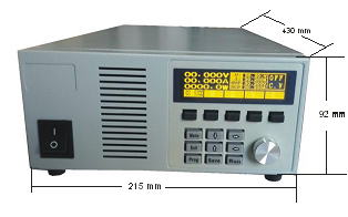
Overall Dimensions

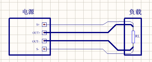
Rear panel output wiring
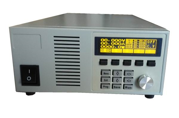
front panel
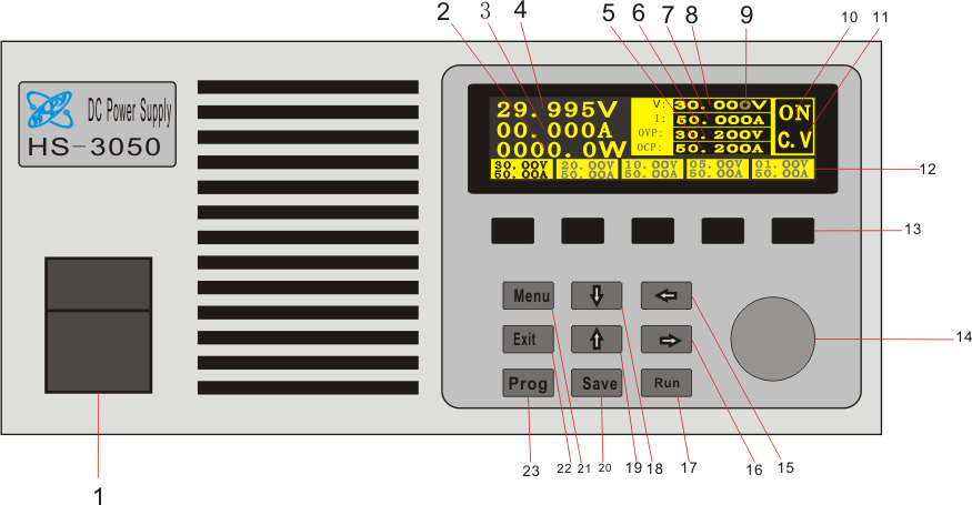
1Power switch
2Power output display
3Current output display
4Voltage output display
5Overcurrent setting
6Overvoltage setting
7Current setting
8Voltage setting
9The cursor indicates the position, and when the cursor moves to that position, the current position will appear darker.
10Power output status
11Constant voltage and constant current indication
12Shortcut Key Content
13Shortcut keys: In the main interface state, press any shortcut key to convert the power to the value set by the shortcut key, adjust the data in the setting window, and pressdown“Save”Jian, the power supply will save the current data to the display button corresponding to the current shortcut key.
14The shuttle adjustment knob allows for free adjustment of the current cursor position data through the knob.
15, cursor movement keys(15-leftThe16-right、17-start、18-down,19up)
20Save the data in the settings window to the shortcut key
21Initialize the interface, pressdown“Menu”Press the key to display a jump to the system initialization settings interface, where initialization parameters can be set arbitrarily. Pressdown“Exit”Press the key to exit the initialization interface and return to the main interface.
22Exit the initialization interface and return to the main interface 23Reserve function keys.
2、 Main technical parameters
input voltage |
AC220±10% |
|
Power efficiency |
80% |
|
output voltage |
DC (0 ~60.000V) |
|
output current |
DC0 ~30.000A |
|
Load adjustment rate |
voltage |
0.02% + 20mV |
current |
0.05% + 10mA |
|
Set value resolution |
voltage |
1mV |
current |
1mA |
|
Read back value resolution |
voltage |
1mV |
current |
1mA |
|
set value accuracy |
voltage |
0.1%+20mV |
current |
0.5%+30mA |
|
Read back value accuracy |
voltage |
0.1%+20 mV |
current |
0.5%+30mA |
|
Ripple and noise |
voltage |
≤50mVrms |
current |
≤200mArms |
|
Read back value temperature coefficient |
50PPM |
|
Instrument size(mm) |
430 X 215 X 92 |
|
Instrument weight (net weight) |
6kg |
|
Common knowledge of using DC power supply
1, DingBasic definitions of voltage mode and constant current mode
The so-called constant voltage mode refers to the working mode in which the current value of the load varies within the rated range, while the output voltage of the DC power supply remains stable, When the load changes and the output current changes, the output voltage remains at the set voltage value and remains unchanged.
The constant current mode refers to the working mode in which the resistance value of the DC load varies within the rated range, while the output current of the DC power supply remains stable, When the resistance value of the load changes and causes a change in the output voltage, the output current remains at the set current value and remains unchanged.
Having constant electricitypress/ The working mode state of a DC power supply in constant current mode should be determined based on the nature of the load. In general, when the load is loaded with rated voltage and the actual load current value is less than the set current value, the DC power supply operates in constant voltage mode; When the actual load current value is greater than the set current value, the DC power supply operates in constant current mode.
The states of constant voltage mode and constant current mode are complementary, that is, the DC power supply either operates in constant voltage mode or in constant current mode. Therefore, before operation, users should first set the required voltage or current value correctly based on the nature of the load and the resistance value of the load, and choose the usage mode that meets the load requirements.
2 Capacitive load application:
Because capacitive loads often cause an increase in output voltage, especially when adjusting the output voltage from high to low, it can lead to a slow decrease in output voltage. Therefore, when using themOutput of DC power supplyConnect a power resistor in parallel and connect it in series between the output and the loadDiode, canObtain better usability. (See the figure below)

3 Inductive load application
When switching on or off a DC power supply or changing the output voltage, inductive loads can generate reverse induced electromotive force, affecting the operation of the DC power supply and even causing damage to it. At this timeOutput of DC power supplyConnect one in series between the end and the loadA diode, and inThe load end is composed of a power resistor and a capacitor connected in parallelRCAbsorption circuit can effectively protect DC power supply.(See the figure below)

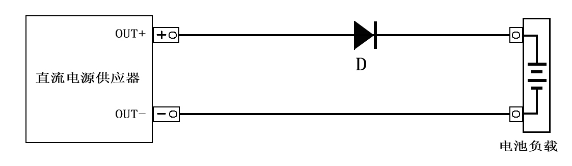
4 Battery load application
When a DC power supply is used to charge battery loads, in order to prevent damage to the power supply caused by misconnecting the polarity of the battery, a diode should be connected in series between the power supply and the battery to protect the safe use of the DC power supply.(See the figure below)
5、 Pulse type load application
The peak current of pulse type loads is within the rated output current range of the DC power supply, or the load current waveform of pulse type circuits or motor drive circuits is within the nominal value (average value) indicated by the measuring equipment. The current will also reach the rated current range of the DC power supply, causing the output voltage to drop or appear unstable. The solution is to connect an inductor in series between the power supply and the load, or choose a DC power supply with a larger output current.
If the pulse width of the pulse type circuit is narrow or the peak current is small, a large capacity capacitor can be installed at the load end to improve it ,Can be done according to1 Ampere approximately 1000UFSelect capacitors.(See the figure below)

6 canApplication of loads that generate reverse current
When the motor connected to the output terminal of the DC power supply suddenly brakes, a large reverse current will be generated. Due to the inability of the DC power supply to absorb the reverse current generated from the load terminal, the output voltage will rise. The solution is toOutput of DC power supplyConnect one in series between the end and the loadA diode is connected in parallel with a discharge resistor at the load end to absorb reverse current. When the reverse current is a sharp spike, please connect a large capacity electrolytic capacitor in parallel at both ends of the load.(See the figure below)

Our company's series of DC power suppliesCan meet the normal usage requirements of users with different types of loads such as resistive, capacitive, and inductive. However, due to the differences in the properties of resistive, capacitive, and inductive loads, corresponding measures still need to be taken for different load properties in specific applications in order to achieve the best usage effect!
Product Warranty
Our company is responsible for free repair or replacement within twelve months from the date of shipment if the quality is lower than the product standard due to the user's compliance with transportation, storage, and use rules. Beyond the warranty period, our company provides lifelong maintenance services and only charges for production costs.