-
E-mail
tao.xu.rl@pgeneral.com.cn
-
Phone
18001075583
-
Address
No. 3 Pingsan Road, Pinggu District, Beijing
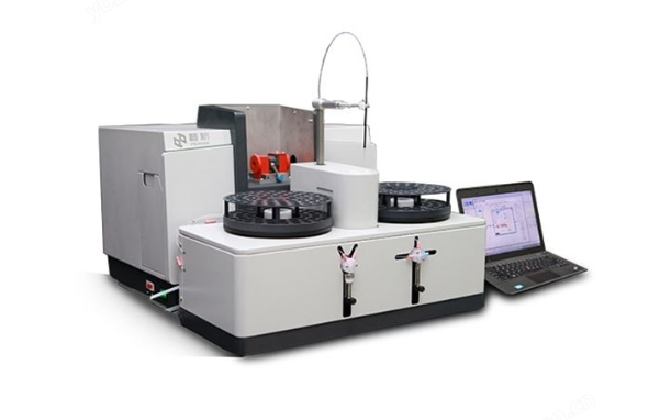
Beijing Puxi General Instrument Co., Ltd
Inspection work before using the automatic lead cadmium analyzer
Date: 2025-09-22Read: 72
The following is a detailed explanation of the inspection work before using the automatic lead cadmium analyzer:
1、 Power and electrical system inspection
1. Power supply stability verification: Confirm that the laboratory power supply voltage meets the range indicated on the instrument nameplate (usually AC 220V ± 10%), and use a multimeter to measure whether the actual voltage value meets the standard. Check the grounding of the socket to ensure reliable grounding and prevent the risk of leakage. For equipment equipped with voltage regulators, their compensation ability during voltage fluctuations needs to be tested.
2. Line integrity inspection: Carefully check along the power line path for any damage to the outer skin, loose joints, or aging cracks. Focus on checking the power interface on the back and side of the instrument to ensure that the plug is tightly connected to the socket without any loose connections. If the insulation layer is found to be damaged, the dedicated power cord should be replaced immediately to avoid the risk of short circuit.
3. Switch function test: Turn on the main power switch of the instrument and the sub control switches of each module in sequence, and observe whether the indicator lights are on normally. Repeatedly turn on and off the power supply multiple times to verify the reliability of the switch contact points and eliminate the problem of poor contact caused by oxidation. Pay special attention to the effectiveness of the emergency stop button to ensure that it can instantly cut off all power supply when pressed.
2、 Sealing detection of gas path system for automatic lead cadmium analyzer
1. Visual inspection of gas pipelines: Check all connecting pipelines one by one along the direction of gas flow, including the main gas supply pipe, branch pipes, and end capillaries. Look for signs of distortion, creases, indentations, or foreign object obstruction. Focus on checking the detachable part of the sleeve type joint to confirm that both clamps are in place and evenly stressed.
2. Pressure attenuation test: After closing all outlet valves, fill the system with inert gas to the rated working pressure and maintain a constant pressure state for no less than 30 minutes. Continuous monitoring of changes in pressure readings during the period indicates the presence of minor leakage points if a significant downward trend is observed. At this point, the leakage source can be located by segmented pressure build-up, and common methods include soap water application or ultrasonic leak detector assisted detection.
3. Filter efficiency evaluation: Remove the gas filtration devices at all levels and check the surface contamination and color change of the filter element. For situations where there is excessive accumulation of coarse particles in the pre filter, it should be promptly rinsed with clean water and dried; If the color of the precision filter deepens, a new filter element needs to be replaced to ensure gas purity. When reinstalling, ensure that the sealing ring is intact and installed in place.
3、 Optical component calibration confirmation
1. Light source intensity verification: After preheating the excitation light source for 15 minutes, use an optical power meter to measure the energy density of the emitted beam. When comparing the measured values with the factory calibration values and the deviation exceeds ± 5%, the aperture size of the diaphragm should be adjusted or the aging lamp tube should be replaced. At the same time, check the wavelength accuracy of the monochromator and verify whether the offset of the characteristic spectral lines is within the allowable range through a standard filter.
2. Consistency of detector response: Inject a standard solution of known concentration into the sample pool and record the stability and repeatability of the peak signals of each channel. If the reading of a certain channel fluctuates abnormally, it may be caused by unstable high-voltage power supply of the photomultiplier tube, and it is necessary to check whether the voltage divider resistor network is balanced. In addition, it is necessary to confirm the uniformity of the coating on the inner wall of the integrating sphere to avoid measurement errors caused by diffuse reflection differences.
3. Optical path collimation adjustment: Use an auto collimator to correct the position relationship between the objective lens and the slit, ensuring that the laser beam propagates strictly along the main axis. Fine tune the angle of the reflector to accurately land the reference spot on the central target surface of the detector, forming a clear circular spot image. This step is crucial for ensuring measurement sensitivity, especially when analyzing low content samples that require precise alignment.
4、 Automatic lead cadmium analyzer flow path system patency test
1. Performance evaluation of pump body: Start the peristaltic pump and run it without load, listen to the running sound to determine if there is any abnormal noise. Touch the pump head with your hand to sense the amplitude of vibration. Excessive vibration may indicate severe bearing wear. Measure the actual flow rate and compare it with the set value. If the error exceeds ± 10%, clean the pump tube or replace the worn roller component.
2. Flexibility test of valve opening and closing: Manually operate all solenoid valves and electric valves to feel whether the action is smooth and without any jamming. Observe whether there are any signs of wear on the valve core sealing ring, and if necessary, apply an appropriate amount of silicone grease to improve the sealing effect. Pay special attention to the position switching accuracy of the multi way valve to ensure full isolation and no cross contamination between different flow paths.
3. Maintenance of pipeline cleanliness: Disassemble key components such as the six way valve and quantitative ring of the injection system, and soak them in dilute nitric acid to remove residual metal ions. Ultrasonic cleaning of the entire flow path pipeline, with a focus on removing particle blockages at the needle valve. Finally, rinse thoroughly with ultrapure water until the conductivity stabilizes, proving that there is no detergent residue.
5、 Verification of the effectiveness of safety protection devices
1. Test of protective cover closure interlock mechanism: Manually block the beam path of the safety interlock sensor to verify whether the instrument can immediately stop exposure and pop up a fault prompt. Repeatedly testing multiple times to ensure that any accidental opening of the protective door is promptly stopped, protecting operators from direct radiation injuries.
2. Emergency exhaust system linkage test: Manually activate the emergency exhaust button, check if the fan speed reaches the maximum value, and effectively discharge the exhaust gas outdoors. Measure the exhaust velocity to confirm that the air exchange rate meets safety regulations, and verify whether the toxic gas sensor can correctly identify the target pollutant and trigger an alarm signal.
3. Availability check of personal protective equipment: Check whether the emergency supplies such as gas masks and rubber gloves in the first aid kit are complete and effective. Test the water flow fluency of the eye wash and the coverage area of the spray device to ensure that emergency measures can be taken quickly in case of sudden chemical spills to reduce the degree of injury.