-
E-mail
879367234@qq.com
-
Phone
18861632831
-
Address
No. 5 ASEAN Road, ASEAN Science and Technology Industrial Park, Nanzha Town, Jiangyin City, Jiangsu Province
Jiangsu Ankerui Electric Appliance Manufacturing Co., Ltd
Application of AM series microcomputer protection device in the distribution engineering of natural gas recovery stations in the Middle East region
Date: 2025-08-05Read: 10
Abstract:The microcomputer protection device can effectively monitor the operation status of the power system and record in real time the faults that occur in the power systemType and Parameters,Thus providing effective reference for the rapid handling of faultsaccording toThis article introducesAM seriesMicrocomputer protection device forNatural gas recovery station power distribution projectDifferent protection objects provide corresponding protection functions,Improving the reliability, safety, and power supply quality of substation operation is beneficial for achieving comprehensive automation of substations and achieving unmanned or few person duty.
KeywordsMicrocomputer protection;monitor;reliability;safety
1 Overview
thatThe natural gas recovery project is a power distribution project undertaken by Chengdu Chijun Co., Ltd,thiscompanyWe are a high-tech enterprise specializing in the research and development, production, sales, and service of power transmission and distribution equipment, control equipment, and box type substation enclosures. The company attaches great importance to quality management and has passed the ISO9001:2015 quality management system certification (certification number: 117.17 Q0 0034-05 ROS), covering the production of box type substations and switchgear, as well as wooden packaging services. Simultaneously emphasizing technological innovation and actively carrying out research and development work, multiple scientific research achievements have been made in the field of exterior design of box type substations.
The power distribution project of this natural gas recovery station is located atMiddle EastThe switchgear in the 6kV medium voltage switch station adopts KYN28-12 cabinet type, modular structure, which is easy to expand and maintain. Adopting a dual power supply system without busbars, it has one busbar PT cabinet, six compressor outlet cabinets, one backup cabinet, and one capacitor outlet cabinet. The overall project covers multiple protections such as current, voltage, and grounding faults, meeting the requirements of medium voltage distribution systems. The protective devices are arranged on the switchgear, and the switchgear is controlled on-site.
2productRequirements andplan
This time, different microcomputer protection devices are configured for different objects in the natural gas recovery station power distribution project, and customized protection functions and language displays that meet the requirements of foreign power supply systems. The entire project is equipped with 11 AM series microcomputer protection devices from Ankerui. The following is the schematic diagram of the microcomputer protection for medium voltage and low voltage distribution rooms:


image1 Diagram of Medium Voltage System

image2 Medium Voltage Distribution Layout Plan

image3 Low voltage system diagram
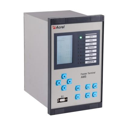
The project is equipped with AM6-L line protection device in the incoming cabinet, AM6-M motor protection device in the motor cabinet, AM6-C capacitor protection device in the capacitor outgoing cabinet, AM6-UB voltage monitoring device in the PT cabinet, AM6-B backup automatic switching protection device in the medium voltage interconnection cabinet, and AM5-DB low-voltage backup automatic switching device in the low voltage interconnection cabinet.These microcomputer protection devices mainly achieve the following protection functionsThe project switchReal time monitoring and protection of cabinet equipment operation:
product image |
Product Model |
Product features |
|
|
AM6-L Line protection device |
50: Instantaneous overcurrent 51: Overcurrent during communication time 50N: instantaneous overcurrent at neutral point 51N: Neutral time overcurrent 50BF: Circuit BreakerFailure protection(DO7output) 59: Overvoltage relay 27: Undervoltage relay (59+27 overvoltage/undervoltage DO4)output) 47: Phase sequence or phase balance voltage relay 86: Lock relay(When the protection function of the protective device is activated,DO5Output is sufficient) TCS: Trip Circuit Monitoring(X6.21 X6.25output) Protection action signal (DO3)output) |
|
AM6-M Motor protection device |
50: Instantaneous overcurrent 51: Overcurrent during communication time 50N: instantaneous overcurrent at neutral point 51N: Neutral time overcurrent 50BF: Circuit BreakerFailure protection(DO7output) 46: Reverse phase or phase balanced current relay 48: Non sequential relay 49: Machine or transformer thermal relay 50G: Instantaneous overcurrent grounding fault relay 51LR: Lock rotor relay 86: Lock relay(When the protection function of the protective device is activated,DO6Output) TCS: Trip Circuit Monitoring(X6.21 X6.25output) 59: Overvoltage relay 27: Undervoltage relay |
|
|
AM6-C Capacitor protection device |
50: Instantaneous overcurrent 51: Overcurrent during communication time 50N: instantaneous overcurrent at neutral point 51N: Neutral time overcurrent 50BF: Circuit BreakerFailure protection(DO7output) 50G: Instantaneous overcurrent grounding fault 86: Lock relayWhen the protection function of the protective device is activated,DO5Output) TCS: Trip Circuit Monitoring(X6.21 X6.25output) 59: Overvoltage relay 27: Undervoltage relay |
|
|
AM6-B Backup automatic switching protection device |
59: Overvoltage relay 27: Undervoltage relay 25: Check the same period Dual power switching with self switching and self recovery/self switching but not self recovery, capable of achieving synchronous grid connection and asynchronous backup switching functions |
|
|
AM6-UB PT monitoring device |
Zero sequence voltage protection, the outlet does not maintain X6.36-X6.33; Bus voltage protection, if any phase voltage in the three-phase voltage is greater than the set value, the outlet will not maintain X6.36-X6.34 |
|
|
AM5-DB Low voltage backup automatic switching device |
59: Overvoltage relay 27: Undervoltage relay 25: Check the same period Dual power switching with self switching and self recovery/self switching but not self recovery, capable of achieving synchronous grid connection and asynchronous backup switching functions |

3 Program Customization
Each microcomputer protection not only has the functions required for different application scenarios, but also needs to customize programs according to the actual situation of the project to adjust the conditions of some protection functions to meet project requirements.
The line protection, capacitor protection, and motor protection configured in the medium voltage system not only need to have functions such as quick break, overcurrent, zero current, overvoltage, and undervoltage, but also need to integrate functions such as circuit breaker failure protection, closing interlock, and trip circuit monitoring. At the same time, these functions require independent relay output nodes to meet different electrical interlocking requirements. In addition, the device has added a fault status input display function for real-time monitoring of abnormal operating status of other associated switchgear.
The PT monitoring device configured in the PT cabinet is equipped with a customized bus voltage protection function, which is independent of the zero sequence voltage protection and set as a transient node. During debugging, it was found that there were occasional misoperations in the output of the relay for this function when the bus voltage was applied and the zero sequence voltage protection was not triggered. After investigation and confirmation of non program and hardware issues, through analysis of device waveform data, on-site power transmission process, and power transmission equipment, it was determined that the fault was caused by the unstable operation of the split type voltage regulator, resulting in serious interference and causing the protection outlet to close incorrectly.
For power supply systems without busbars for two incoming lines, whether it is a medium voltage system or a low voltage system, line protection needs to be configured in one incoming cabinet, and a backup automatic switching device needs to be configured in the other incoming cabinet. The backup automatic switching mainly realizes the functions of checking the synchronous closing and switching, and not checking the synchronous backup automatic switching. Whether it is necessary to check the synchronous is controlled by a momentary button, and the signal of this button is connected to the input amount of the comprehensive protection device. Due to the transient nature of the signal, in order to ensure the complete execution of the backup automatic switching process, it is necessary to add a configurable return delay in the program to maintain the signal. In addition, considering the difference in load types between medium voltage systems and low voltage systems, the inspection of low voltage systems is the sameThe period function also adds a negative sequence voltage criterion, making the synchronization conditions more stringent and reliable.
(1) For the synchronous closing and switching function, the device detects that the "synchronous grid connection" status is closed, and determines whether the two incoming lines are in the synchronous state, that is, whether the voltage amplitude, phase, frequency and other parameters of the two incoming lines are within the set allowable range. After confirming that the synchronous conditions are met, the backup automatic switching device first closes the backup incoming circuit breaker, and then opens the main supply incoming circuit breaker to complete the power switching operation. This logic ensures a smooth transition between the two power sources while strictly meeting electrical parameter matching requirements.
(2) When the device detects that the "non synchronous backup switching" state is closed, it realizes the logic of automatic switching of incoming backup and mutual switching of incoming backup, in response to the non synchronous backup switching function. In the automatic switching mode of the incoming line backup, there is a distinction between the main and backup lines. When the main incoming line loses power, the main incoming line circuit breaker is disconnected first, and then the backup incoming line circuit breaker is closed; If the main power supply is restored, first disconnect the backup incoming circuit breaker and then close the main incoming circuit breaker. In the mutual input mode of incoming lines, there is no distinction between main and backup lines. If any incoming line loses power, it will switch to the other incoming line for power supply, and the existing power supply mode will remain unchanged after power is restored. Both modes ensure safe power switching under non synchronous conditions.
4sceneapplication
The microcomputer protection of this project is installed locally and dispersed in various heights, lowOn the pressure switch cabinet, the on-site installation is shown in the following figure. This projectThe required protection function has been verified to be correct.


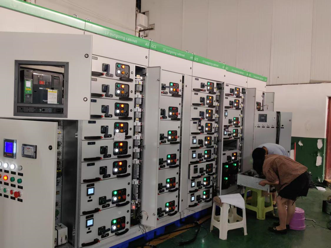
image4On site installation pictures
5 Conclusion
The adoption of microcomputer protection devices in the power system is an inevitable trend in the intelligent development of the power grid. Compared with traditional relays, although the price of microcomputer protection is relatively high, it can greatly improve the reliability, safety, and power supply quality of substation operation, which is conducive to achieving comprehensive automation of substations, realizing unmanned or few person duty, and greatly saving costs in another way. This article introducesMiddle East Natural Gas Recovery Station Power Distribution ProjectBy installing various protective objectscustomizationThe protective device not only achieves comprehensive automation of the entire power distribution project, but also effectively reduces the labor intensity of workers and improves the reliability of equipment operation.
References
[1] Ankerui Enterprise Microgrid Design and Application Manual, June 2020 Edition
[2] Design and Product Secondary Principle Atlas of Ankerui 35KV and Lower Substation Intelligent Distribution System. October 2020 Edition
[3] Ankrui User Substation Comprehensive Automation and Operation and Maintenance Solution. November 2021 Edition