-
E-mail
879367234@qq.com
-
Phone
18861632831
-
Address
No. 5 ASEAN Road, ASEAN Science and Technology Industrial Park, Nanzha Town, Jiangyin City, Jiangsu Province
Jiangsu Ankerui Electric Appliance Manufacturing Co., Ltd
Application of Acrel1000DP Distributed Photovoltaic Monitoring System in Pinggao Food 4.4MW Photovoltaic Project
Date: 2025-09-01Read: 10
Liu Chuan
Jiangsu Ankerui Electric Appliance Manufacturing Co., LtdDepartment
pick To:In“doublecarbon”Under the background of the construction of new power systems, the proportion of distributed photovoltaic access continues to increase, which has a strong impact on the voltage, scheduling operation, and peak shaving of the distribution network. This article design includes platform layerequipmentlayertwoA distributed photovoltaic control platform with a layered architecture system, as well as local and remote communication solutions for small capacity industrial and commercial distributed photovoltaics, and research on key technologies such as the construction of distributed photovoltaic acquisition models, multi-source data fusion estimation, and active and reactive power optimization control for distributed photovoltaics, have been achievedSmall capacity industrial and commercial distributed photovoltaicsObservable, measurable, adjustable, and controllable..
Keywordsdistributed photovoltaicPhotovoltaic control platformRemote communication
1. Overview
Shanghai Huadian Fengxian Pinggao Foodproduct4408.085kwp Distributed photovoltaic power generation project (hereinafter referred to ascall, name, say, weigh“This itemeye”)It is a response countryhome“Optimize the energy structure and provide cleaner and more reliable energysource”The call for investment and construction of distributed photovoltaic power generation application demonstration projects. Shanghai Huadian Fengxian New Energy Co., Ltdcall, name, say, weigh“Shanghai Huaelectricity”)Renting the roof of the factory building of Shanghai Pinggao Food Co., Ltdset4408.085kWpRoof distributed photovoltaic power generation project, adoptinguse“Spontaneous self use, surplus electricity onnet”plan
thisIntroduction to the articleDemonstration of photovoltaic power station access system scheme, research on system relay protection and safety automatic device, system communication, system scheduling automation scheme, etc.

image Project Site Acceptance Diagram
2. Current situation of the power grid
This project is located on Hangtang Road in Fengxian District, Shanghai 1618 Number belongs to the management scope of Fengxian Power Supply Company of Shanghai Electric Power Company. At present, the user's distribution station is 10kV Voltage user station, in station 4 Taiwan 10kV Transformer, with a capacity of(1250+1600)kVAand(1250+1600)kVAUser A's transformer passes through 10kV lineroad“22 Pinggao FoodArmor”Line access to Likuofu switching station 10kV A section of busbar, then connect againpass“Liang 19 likofuArmor”Line access 35kV Liang Dianstand10kV A section of busbar. User B's transformer passes through 10kV lineroad“32 Pinggao FoodB”Line access to Likuofu switching station 10kV Second section busbar, then connect againpass“Liang 33 likofuB”Line access 35kV Liangdian Station 10kV Three section busbar.
The capacity of photovoltaic modules in this project is 4408.085kWpAccording to the "Typical Design of State Grid Distributed Photovoltaic Power Generation Access System" and the site conditions, this project is 2 At the grid connection point, the photovoltaic modules are connected to the high-voltage distribution cabinet on the high-voltage side of the user's photovoltaic station after inversion. User photovoltaic through 10kV Connect the lines separately 35kVLiangdian Station 10kV A section of busbar and 35kV Liangdian Station 10kV Three section busbar.
Shanghai Huadian Fengxian Pinggao Foodproduct4408.085kwp The schematic diagram of the access plan for distributed photovoltaic power generation projects is as follows:
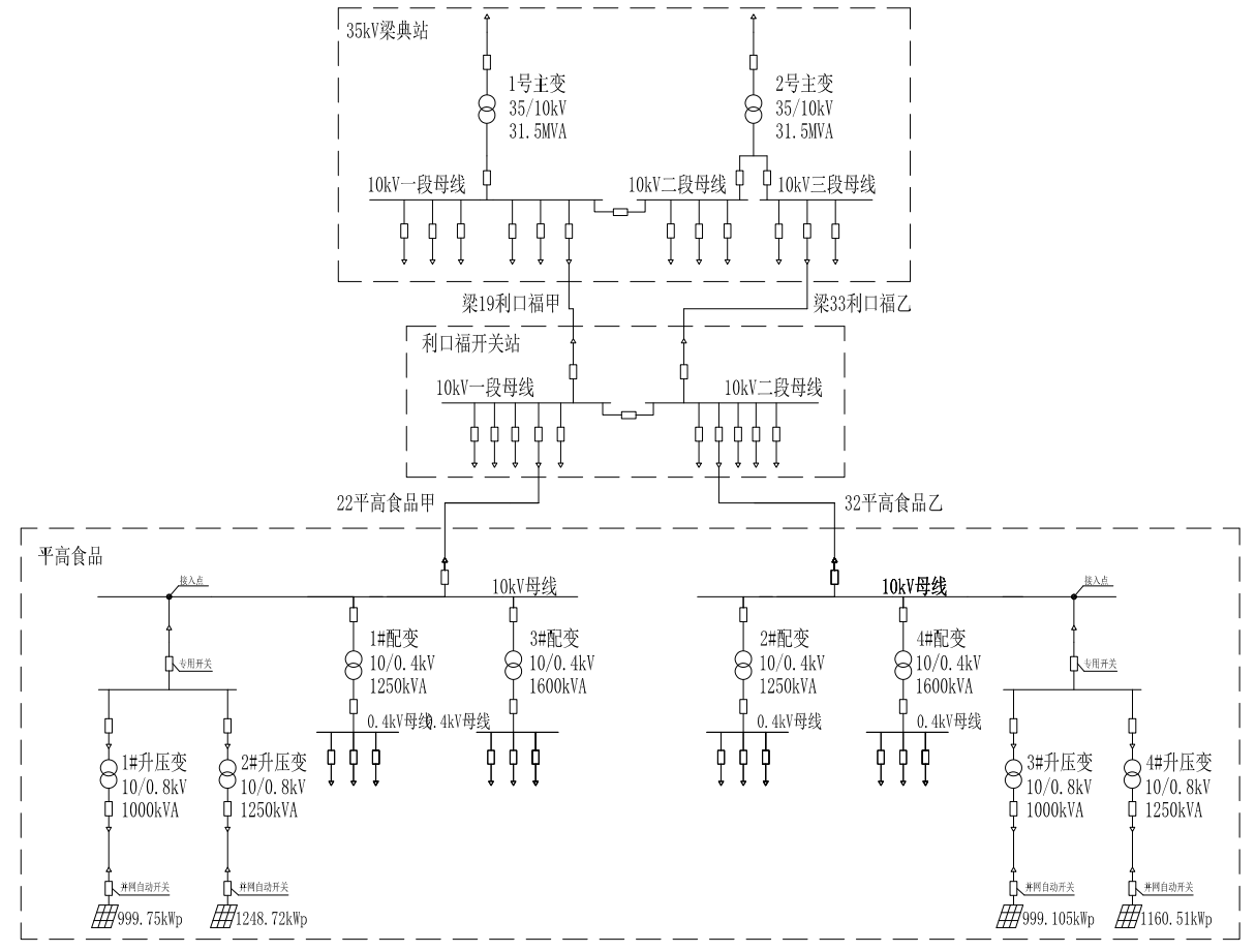
image Schematic diagram of access scheme for distributed photovoltaic power generation project
3. Technical Solution
The scale of this project is approximately 4408.085kWpUtilize the roof of the factory building to construct a photovoltaic power generation system, with key equipment such as photovoltaic modules, inverters, transformers, etc. using domestic products. The power generated by the distributed photovoltaic system is consumed locally, self generated, and the surplus electricity is connected to the grid. This project is divided intofor4A photovoltaic power generation subsystem, corresponding to the photovoltaic power generation systementer2Taiwan1000kVAstep-up transformerand2Taiwan1250kVAstep-up transformer.1#boostchange1000kVAThe power generation unit adoptsuse3Taiwan300kWString inverter;2#boostchange1250kVAThe power generation unit adoptsuse4Taiwan300kWString inverter;3#boostchange1000kVAThe power generation unit adoptsuse3Taiwan300kWString inverter;4#boostchange1250kVAThe power generation unit adoptsuse4Taiwan300kWString inverter, which converts DC power into three-phase AC power.14Taiwan300kWThe inverters are respectively connected to the low-voltage side of the corresponding capacity boost converter, and are boosted by the boost converterto10kV.4A photovoltaic power generation unityuan1,2,3,4#Boost converter, passpass2return10kVCable is sent to the photovoltaic switch stationinside10kVConfluence busbar. The photovoltaic switch station adopts a single busbar connection and is connectedpass2Return line and original substationplace10kVa section of busbar;10kVNew intervals have been added for the splicing of the second section busbar and connected to the power grid.
3.1. Introduction to a System
This project is newincrease10kVTwo switch stations and distribution equipmenttogether14High voltage cabinets, including: accesscabinet2Surface and grid connectioncabinet2Surface and measurementcabinet2noodlesThePTcabinet2Surface and photovoltaic incoming linescabinet4Surface and reactive power compensationcabinet2The surface adopts a single busbar connection and is integrated into the power grid.
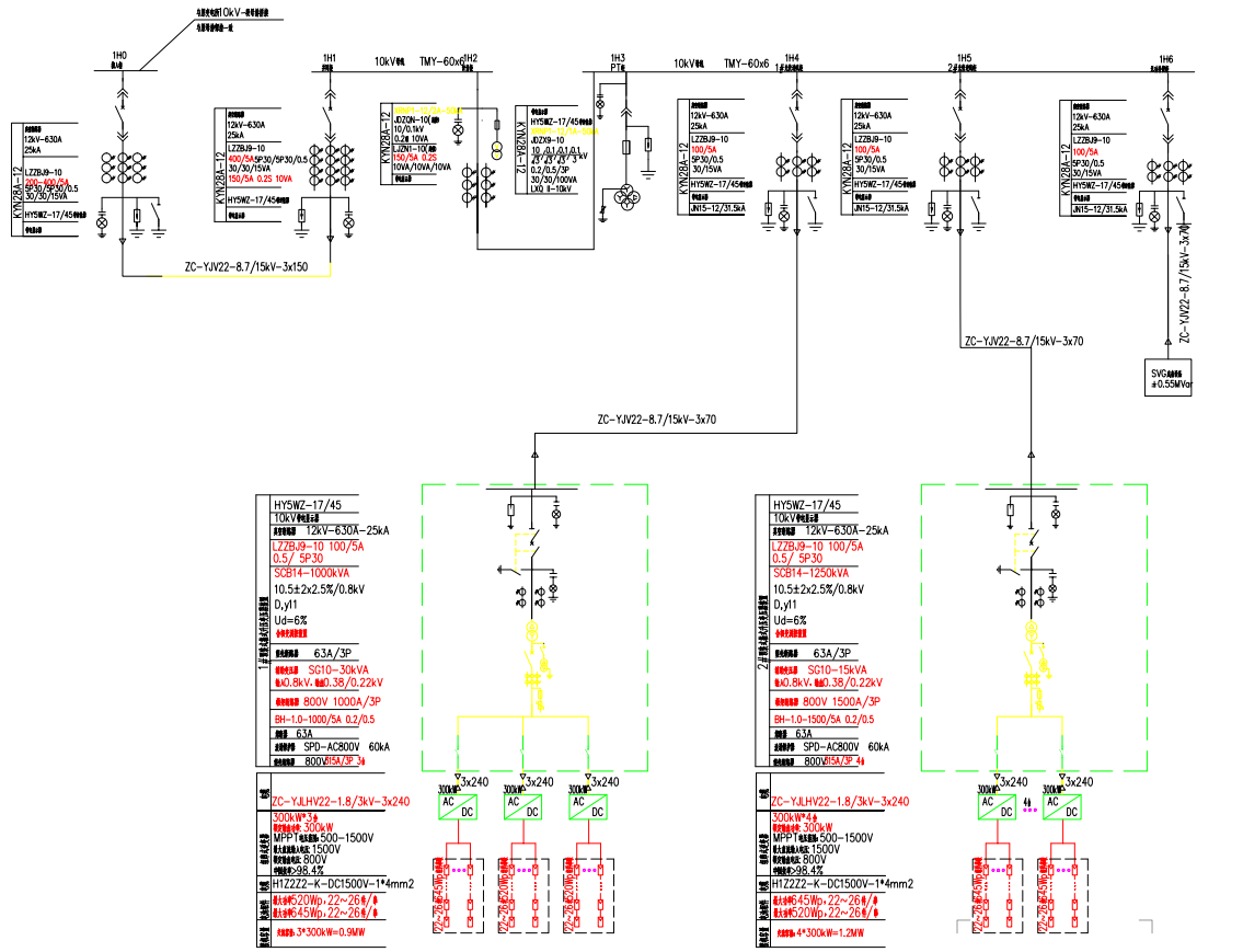
image newbuild1#Grid point photovoltaic primary diagram
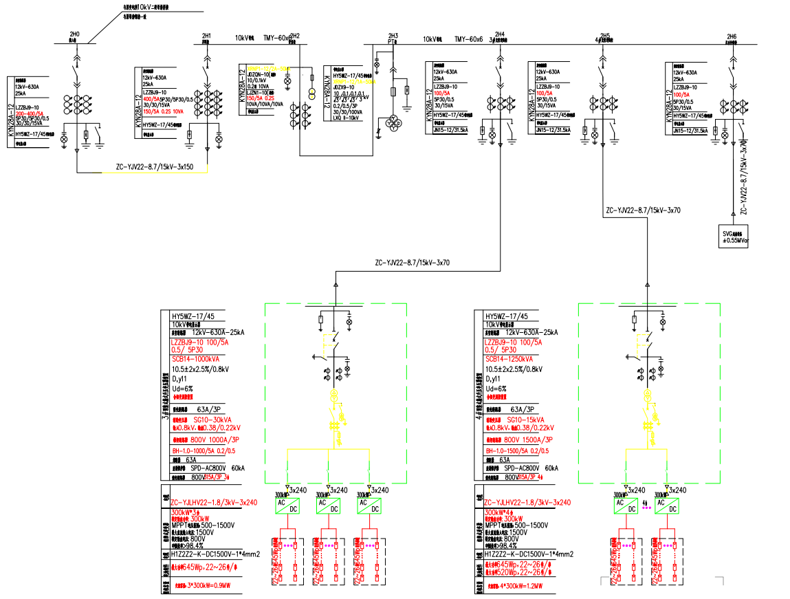
image newbuild2#Grid point photovoltaic primary diagram
3.2. Original configuration of relay protection and safety automatic devicesthen
The main electrical equipment in this photovoltaic power station adopts microcomputer protection to meet the requirements of information transmission. Component protection shall comply with the Technical Regulations for Relay Protection and Safety Automatic Devices(GB14285-2006)ConfigurationImplement relevant design technical regulations and provisions, implement the configuration and anti accident measures of State Grid Corporation of China's system relay protection and safety automatic devices, and make full use of existing system relay protection devices as much as possible.
1)Line protection
According to the "Typical Design of Distributed Power Access System", when a short circuit fault occurs in the photovoltaic power station line of this project, it is required that there is a line protection that can quickly act and instantaneously trip the corresponding circuit breaker (i.e. the photovoltaic incoming cabinet circuit breaker of the photovoltaic power station), meeting the requirement of fast and reliable fault removal for the entire line.
According to the actual situation of this project, reverse power protection will be installed on the photovoltaic station side, with the direction pointing towards the step-up transformer. Access cabinet configurationplace1Install directional overcurrent protection device, including directional overcurrent protection, with the direction pointing towards the grid connected line. The protection device has functions such as directional current quick break, overcurrent protection, overload protection, zero sequence current protection, etc. When a short circuit fault occurs in the grid connected line of the photovoltaic power station, the line protection can quickly trip the corresponding circuit breaker, meeting the requirements of quickly and reliably cutting off the fault in case of a full line fault.
2)Busbar protection
The photovoltaic power station adopts a single busbar connection. When the busbar output fails, the directional overcurrent protection configured at the busbar switch will cut off the fault, and no separate busbar protection will be configured.
3)Anti islanding measures
The inverter in the photovoltaic power station needs to have anti islanding protection function. The anti islanding protection of the inverter mainly includes detection methods such as frequency offset, power variation, voltage phase jump, etc., and the action timeIn100ms~1sIsland phenomenon protection is an important and high priority protection in inverter grid connection protection, which requires photovoltaic systems to be protected in the event of grid failurepress2sStop supplying power to the power grid lines within.
Re allocation of grid connection points for photovoltaic power stations in this phaseplace1Set up an independent anti islanding protection device, which operates on the grid switch on the side of the photovoltaic power station. The independent anti islanding protection device should include overvoltage and low voltage protection functions, as well as over frequency and low frequency protection functions. It should have the ability to quickly monitor islanding and immediately disconnect from the power grid. The anti islanding protection action time is not longYu2sThe anti islanding protection should be coordinated with the reclosing of the power grid side lines and the action time of the safety automatic device.
4)Emergency control of frequency and voltage
This issue is distributed on the side of the photovoltaic power stationplace1Set the frequency and voltage emergency control device to trip the photovoltaic grid switch when the frequency and voltage exceed the allowable range.
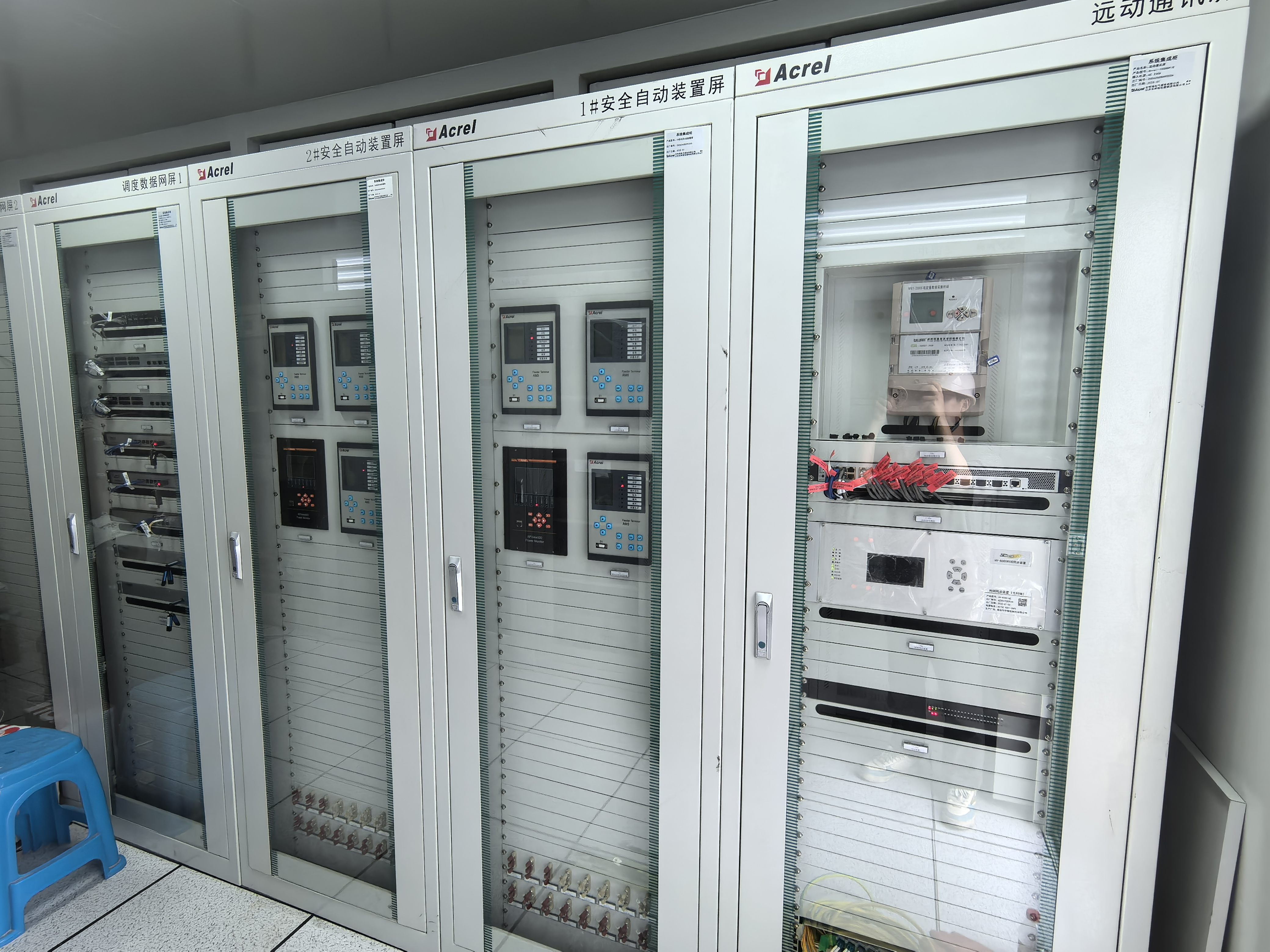
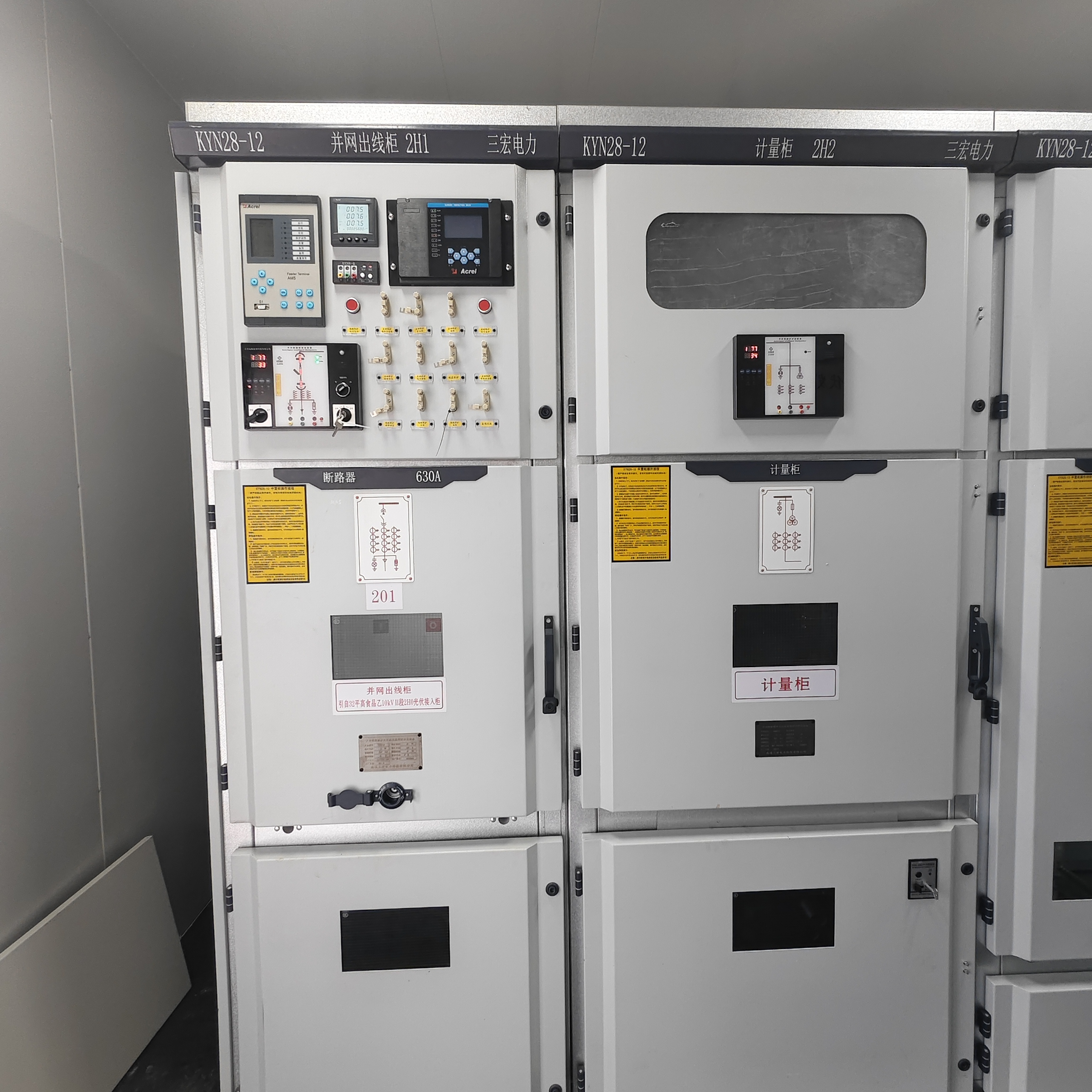

image Physical picture of relay protection and safety automatic device on site
4. system architecture
The configuration of the photovoltaic power station in this project1Provided by Tao'an Kerui Electric Co., LtdofAcrel-1000DPThe distributed photovoltaic power monitoring system has functions such as protection, control, communication, and measurement, and can achieve comprehensive automation management of photovoltaic power generation systems and switch stations. The status signals of inverters, high and low voltage equipment, etc. in this project must be connected to this monitoring system.
The photovoltaic power station monitoring system of this project consists of two parts: the station control layer and the local layer, with an open layered and distributed network structure. The monitoring system communicates with the local layer through Etherneteven,According to different functions and systems, the geological strata are distributed in the inverter area or transformer box in a relatively independent manner. In the event of station control layer and network failure, the geological strata can still independently monitor various electrical equipment on site. Computer monitoring system through remote controlCommunication devices are connected through specialized channelsThe Internet and Shanghai Cityscheduling platformimplementremoteCommunication.
The station control layer is connected by a computer networkMonitoring host andOperator station, remote controlCommunication deviceThe system is composed of various components, providing a human-machine interface for on-site operation, realizing functions such as management and control of geological equipment, forming a monitoring and management center for the entire station, and having an interface for communication with remote control centers.
The geological equipment consists of intelligent measurement and control units, network system communication units, inverter data acquisition units, multifunctional energy meters, etc. The main electrical equipment includes combiner cabinets (determined by actual design), inverters, box transformers, and grid switches. It directly collects and processes raw data from the site, transmits it to the monitoring station of the station control layer through the network, and receives control operation commands from the station control layer. After validity judgment, locking detection, synchronization detection, etc., it finally controls the operation of the equipment.
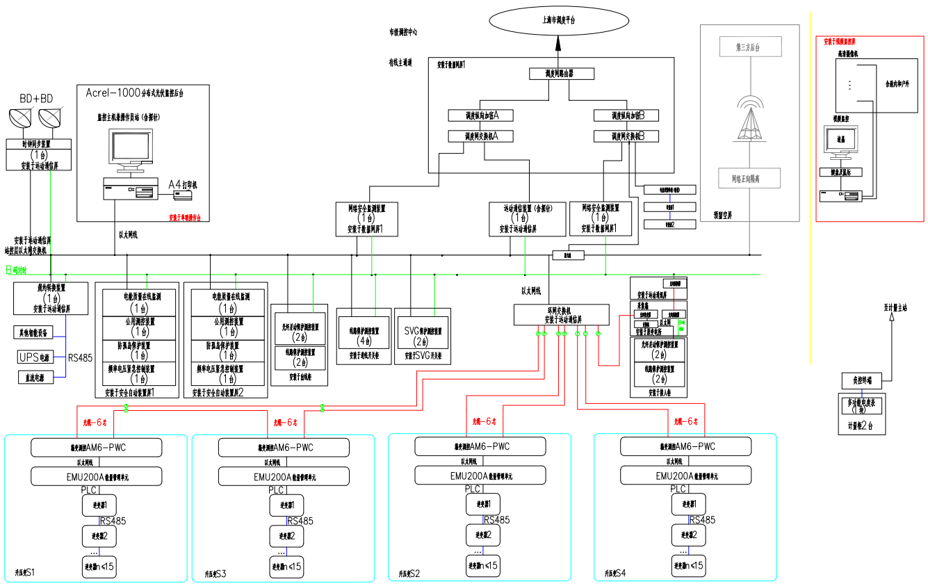
image Network architecture diagram of monitoring system
4.1. 通信方案
This project adopts取EPONProvide a fiber optic cable data transmission channel between the power plant and the dispatch.
In the new photovoltaic power stationincreaseONUsetprepare1set、24Core Light Distribution Sheetyuan1Establish a communication transmission channel from the photovoltaic power station of this project to the Shanghai municipal survey, and connect the non real time electricity information and real-time operation information of the photovoltaic power station to the main station system separately. On site testing of wireless signals meets the requirements and serves as a backup channel.
4.2. scheduling automation
4.2.1Current situation of scheduling automation
Currently located in ShanghaituneD5000The system receives information about the power plantThe500kVThe220kVSubstation and mainwant110kVThe remote control information of the substation mainly comes from the substation computer monitoring system.
4.2.2Scheduling Relationship and Scheduling Management
The electricity generated by this photovoltaic power station is self generated and used, with surplus electricity connected to the grid. The nature of the power generation system is a public photovoltaic system. Considering the particularity of photovoltaic power stations, this photovoltaic power station is designed according to the Shanghai municipal survey.
4.2.3Configuration and Requirements
According to the Technical Regulations for Automated Design of Regional Power Grid Dispatching, the Technical Regulations for Connecting Photovoltaic Power Stations to the Power Grid of State Grid Corporation of China, and the regulations issued by State Grid Corporation of Chinaexhibition(2019)858The State Grid Shanghai Electric Power Company has issued the Technical Principles for Photovoltaic Power Generation Access to the Shanghai Distribution Network and the Plan for State Grid Distributed Power Generation Access SystemHow to translate1
XGF10-Z-1Design the system scheduling automation for this project based on relevant documents such as the plan. The main design scope includes requirements for scheduling system interfaces, photovoltaic power station engineering, and remote control equipment channels for substations within the system, as well as the selection of ancillary equipment.
(
)Scheduling relationship2After the completion of this project, the photovoltaic power station will be designed according to the jurisdiction of Shanghai Municipal Government.
()Electricity billingMeasurement and metering are conducted in accordance with the standards of the power industry6accurateDL/T448-201Technical Management Regulations for Electric Energy Metering Devices and Local Standards in Jiangsu Province2accurate
DB32/991-202Configure according to the requirements of the "Specification for Configuration of Electric Energy Metering Devices" and the "Technical Regulations for Grid Connection of Photovoltaic Power Stations of State Grid Corporation of China".1This project will install primary and secondary billing energy meters on the photovoltaic power station sideeach0.2Block, levelforS1Grade. The main meter serves as the gateway meter for the electricity consumption of the photovoltaic power station, and the relevant data of this gateway meter is synchronously uploaded to the energy metering system of Jiangsu power grid. Distribution at the outgoing cabinet of the photovoltaic power stationplace0.2A levelfor
SThe reference table for the level, with accuracy requirements referring to the measurement at the power generation gateway.The electric energy meter adopts a static multifunctional electric energy meter, which should at least have bidirectional active and four quadrant reactive power metering functions, event recording functions, standard communication interfaces, and the ability to communicate locally and remotely through electric energy information collection terminals. According to the "Specification for Configuration of Electric Energy Metering Devices"2(DB32/991-2020.2)Requirement: The accuracy of the electric energy meter in this project must meet the requirementstoS0.2The secondary measuring winding of the measuring transformer should be dedicated and should not be connected to equipment unrelated to electrical energy measurement. It is required that the accuracy of the current transformer and voltage transformer should be up toto0.2S
、3Grade.
()Power quality monitoring deviceAccording to the requirements of the "Technical Regulations for Connecting Photovoltaic Power Stations to the Power Grid of State Grid Corporation of China" and the "Power Quality Management Regulations of Jiangsu Electric Power Company", the photovoltaic power station side will be fully installed in this phase3footIEC61000-4-30-200Electromagnetic Compatibility0第4-3Partial Testing and Measurement Techniques - Power Quality "Standard RequirementsofA1Class electric energy quality online monitoring device
place4Monitor power quality parameters, including voltage, frequency, harmonics, power factor, etc.
()Photovoltaic power station group control and adjustment system2021According to the 'Electric Adjustment'44[] []numberThe requirements of Article 9 of the "Jiangsu Grid Distributed Power Generation Grid Connection Dispatch Management Work Specification":“Distributed power sources should accept and execute group control and dispatch instructions, and their remote control information, electric energy metering information, and other data should be connected to the dispatch automation system and distribution automation systemunify”1The photovoltaic power station side of this project is equipped as required
placeA distributed power collection and control device with group control and adjustment controller functions, capable of transmitting and issuing group control and adjustment instructions between the upper level dispatch master station and on-site inverter devices.To meet the requirements of power supply group control and adjustment, corresponding data collectors are configured on a box transformer basis. The data collectors collect inverter data and upload it to the photovoltaic power station monitoring system through box transformer measurement and control. The control system should have the ability to respond quickly, in order to adjust system parameters in a timely manner and respond to changes in the external environment, with response time controlIn1minWithin, the response accuracy is smallYu
5. 1.5%
. System functions
5.1.real-time monitoringAcrel-1000DPDistributed photovoltaic monitoringThe system has a user-friendly human-machine interface and can visually display the operating status of distribution lines in the form of a distribution diagram. It can monitor real-time electrical parameter information such as voltage, current, power, and power factor of each circuit, dynamically monitor the closing and opening status of circuit breakers, isolation switches, ground knives, and related fault and alarm signals of each distribution circuit.

At the same time, an overall interface can be designed for users to select the corresponding photovoltaic modules or high-voltage parts of the distribution room for viewing .
image Real time monitoring main interface diagram
5.2.0historical event
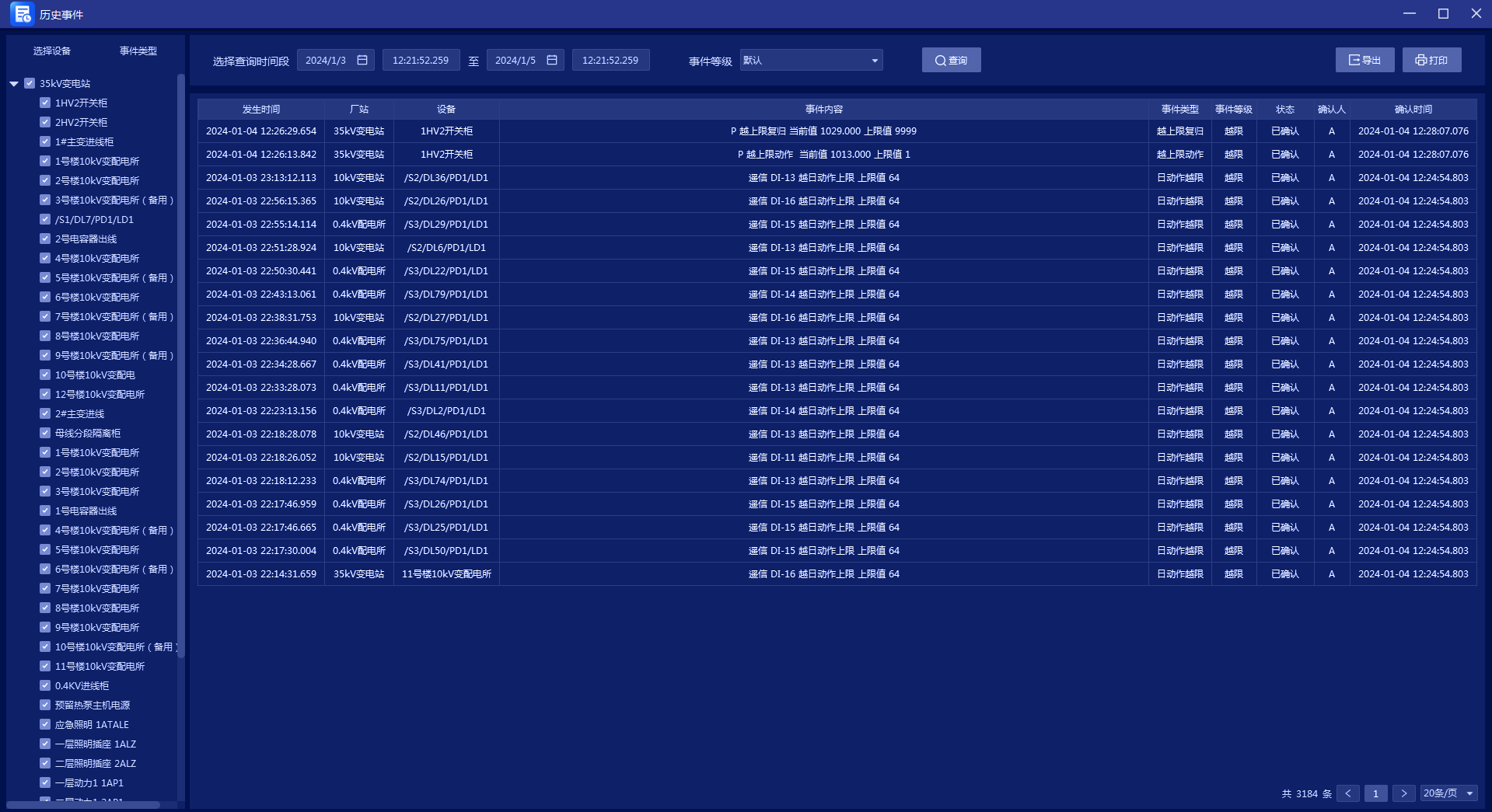
Acrel-200 The power monitoring system can store and manage event records such as remote signal displacement, protection actions, accident tripping, as well as voltage, current, power, and power factor exceeding limits, making it convenient for users to trace, query, and analyze system events and accidents. You can search by time, type, level, and device.
image Alarm interface diagram
5.3.
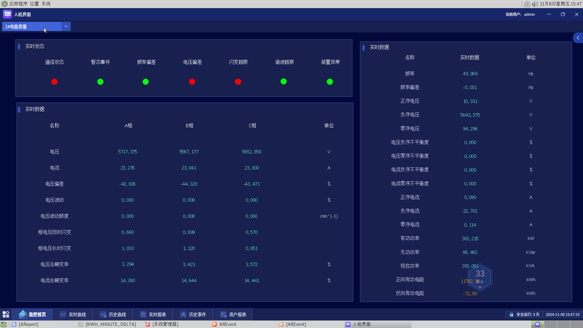
Online monitoring interface for power quality In the power quality monitoring diagram, the operating status of power quality devices, total effective value of current and voltage, voltage fluctuations, total voltage distortion, positive and negative active energy, active and reactive power, and other power quality information can be directly viewed. We can monitor the quality of on-site electricity based on this information and make timely response plans.image
6. Online monitoring interface for power quality
imageConclusionDistributed photovoltaic power generation systems are widely used due to their clean and renewable characteristics, but their power generation exhibits significant instability, which poses a challenge to the stable operation and economic benefits of the power system. Therefore, when connecting distributed photovoltaic projects to the grid, configuration is requiredRelay protection and safety automatic device
and
Accept the regulation of the dispatch master station system, assist in the high proportion and orderly grid connection of distributed photovoltaics, strengthen the unified control of distributed photovoltaics, promote the coordinated operation of distributed photovoltaics and large power grids, and build a new distributed new energy dispatch and management system that is transparent in data, convenient in regulation, and interactive in energy.1References []Tan Dahandsome,.DaiBin.Design and Implementation of Distributed Photovoltaic Control Platform[J]Electrical technology
technique .24(2), 41-51.[2].Yang LiNaThe impact of distributed photovoltaic power generation grid connection on the distribution network.ring[J]Technology capital
message3, 2024,22(11) [.]Wang Wenjing.The current situation and prospects of distributed photovoltaic power generation in China[J]Journal of the Chinese Academy of Sciences