-
E-mail
879367234@qq.com
-
Phone
18861632831
-
Address
No. 5 ASEAN Road, ASEAN Science and Technology Industrial Park, Nanzha Town, Jiangyin City, Jiangsu Province
Jiangsu Ankerui Electric Appliance Manufacturing Co., Ltd
Security upgrade | Low cost, but important: What is the experience of installing "smart seat belts" on electrical circuits?
Date: 2025-12-17Read: 9
Abstract: In order to achieve automatic testing of the electrical performance of electrical fire protection current limiting protectors, a set of automatic testing devices for electrical performance of electrical fire protection current limiting protectors based on LabVIEW has been developed. This device can automatically test the electrical performance of electrical fire current limiting protectors of various specifications such as 0-40A, 0-63A, 160-250A, etc. The testing content includes short-circuit current limiting test, overload protection test, and voltage fluctuation test. The testing device can automatically capture short-circuit current limiting test waveforms and overload protection test waveforms, accurately calculate short-circuit current limiting time and overload protection time, and store waveforms, data, and generate test reports. The electrical fire current limiting protector with a rated working voltage of 220 V and a current of 10A was selected as the test sample for testing. The test results showed that the developed testing device improved the testing efficiency and safety performance, reduced the testing cost, and achieved automation and intelligence of the electrical performance testing of the electrical fire current limiting protector.
Keywords: electrical fire protection current limiting protector; Short circuit current limiting
1. Introduction
In recent years, electrical fires caused by short circuits, overloads, and electrical equipment failures have become a type of fire with high frequency and significant losses among all fires. According to the China Fire Protection Yearbook, the proportion of electrical fires to the total number of fires has been increasing year by year from 2014 to 2017, reaching 35.7% in 2017, posing a great threat to people's lives and property safety. When electrical circuits are short circuited, the existing mechanical circuit breakers often have problems such as slow closing speed, inability to limit short-circuit current, and arc generation during opening, which can lead to the expansion of accidents and trigger electrical fires. For example, the two major fire accidents in Harbin "8.25" and Beijing Daxing "11.18" that caused significant casualties were both caused by electrical circuit short circuits, mechanical circuit breakers failing to reliably protect, and ignition of surrounding combustibles. In order to reduce fire hazards, the Fire Detection and Alarm Technical Committee of the National Fire Standardization Technical Committee, in conjunction with relevant enterprises, has formulated the corresponding national standard "Electrical Fire Monitoring System Part 6: Electrical Fire Protection Current Limiting Protector", which requires that the short-circuit current limiting time of the electrical fire protection current limiting protector should not exceed 150 μ s. Being able to achieve microsecond level current limiting protection for electrical short circuit faults can greatly reduce fire accidents caused by electrical circuit short circuits. At present, the standard is in the approval stage.
In order to achieve synchronous development of testing equipment and approval of testing standards, laying the foundation for the smooth implementation of the standards after they are officially introduced. To this end, based on the testing methods that meet the requirements of the testing standards, we have further improved the testing efficiency and reduced the testing cost. We have designed and developed an automatic electrical performance testing device for electrical fire protection current limiting protectors based on LabVIEW. This testing device can be used to automatically test the electrical performance of various specifications of electrical fire protection current limiting protectors, including short-circuit current limiting testing, overload protection testing, and voltage fluctuation testing. After the testing is completed, a test report is automatically generated, achieving automation and intelligence in the electrical performance testing of electrical fire protection current limiting protectors.
2、 Overall scheme design
2.1 Basis for Scheme Design
According to the relevant regulations on electrical performance testing of electrical fire current limiting protectors in the standard, the short-circuit current limiting test circuit is shown in Figure 1, and the overload protection test circuit is shown in Figure 2. In Figures 1 and 2, GR is the voltage source, TR is the tested sample, S is the single pole single throw switch, R is the 0.01 Ω non inductive sampling resistor, CR is the oscilloscope, T is the button switch, Z1 is the 3-6A resistive load, A in Figure 2 is the clamp ammeter, and Z2 is the 25-50A resistive load.
Short circuit current limiting test steps: Connect the test sample to the device as shown in Figure 1, close switch S, the protector works normally, press the on button switch T, record and observe the voltage waveform at both ends of R displayed on the oscilloscope at the moment of closure, and record the time when the test sample completes the short circuit current limiting.

Figure 1 Short circuit current limiting test circuit
Overload protection test steps: Connect the tested sample to the equipment as shown in Figure 2, insert clamp type ammeter A on the wire, turn on switch S, and record the time when the sample completes overload protection.
Voltage fluctuation testing steps: Arrange the tested sample according to normal working requirements, supply power to the sample at 110% and 85% of the rated voltage respectively, and repeat the above short-circuit current limiting test and overload protection test.

Figure 2 Overload protection test circuit
2.2 Overall Design Proposal
According to the testing method specified in the standard, a set of automatic electrical performance testing device for electrical fire protection current limiting protector based on LabVIEW was designed. The overall design diagram of the device is shown in Figure 3. The test software based on LabVIEW is installed on the industrial computer. The test software collects the voltage on the output side of the voltage regulator and the current in the circuit through the voltage detection module and high-speed current acquisition module, respectively. According to the test content, it automatically controls the output voltage of the voltage regulator, the adjustable load switching resistance value, the KM switch status of the contactor, and whether the short-circuit branch is short circuited.

Figure 3 Overall Scheme Design Block Diagram
3、 Hardware Design
The hardware design mainly includes the selection and design of industrial control computers, power supply units, adjustable loads, high-speed current acquisition modules, short-circuit branches, and voltage detection modules. The industrial control computer uses Advantech's IPC-610L; The adjustable load model is RXF-AC220V 1-64A AC load, and a DC24V relay is installed on the adjustable load. The resistance can be switched by controlling the relay; The high-speed current acquisition module adopts the Guwei MDO-2000E series multifunctional mixed domain oscilloscope, with a frequency bandwidth of 200MHz and a large real-time sampling rate of up to 1GSa/s.
3.1 Power supply unit design
When conducting electrical performance tests on electrical fire current limiting protectors, voltage fluctuation tests are required. The tested electrical fire current limiting protectors are powered at 110% (approximately 242V) and 85% (approximately 187V) of the rated voltage, respectively. Therefore, the power supply unit should meet the requirements of an input voltage of AC 220V and an output voltage of 0-250V, for supplying power to the tested sample and the entire device. The hardware circuit of the power supply unit is shown in Figure 4.

Figure 4 Hardware circuit diagram of power supply unit
The power supply unit consists of a voltage regulator, a stepper motor, and a stepper motor driver. The selected voltage regulator model is TEGGC2J-30KVA, with an input voltage of single-phase 220V, an output voltage of 0-250V, and a rated working current of 120 A. The selected stepper motor driver model is HST884A, which uses DC 24-50V power supply. The industrial computer can adjust the output voltage of the voltage regulator by controlling the stepper motor, avoiding manual operation.
3.2 Short circuit branch design
During short-circuit current limiting testing, the contactor and bidirectional thyristor form a short-circuit branch. When using a bidirectional thyristor as a short-circuit branch, the phase angle at which the short-circuit occurs can be accurately controlled. However, due to the on state voltage drop when the thyristor conducts, it will to some extent limit the growth of short-circuit current. The resistance of the contactor is small when it is conducting, and it will not affect the magnitude of the short-circuit current due to the contactor, but it cannot control the phase angle at which the short-circuit occurs. When there is a requirement for the phase angle of a short circuit, a bidirectional thyristor is selected as the short circuit branch; When there is no requirement for the phase angle of the short circuit, a contactor is selected as the short circuit branch. The hardware circuit of the short-circuit branch is shown in Figure 5. The selected bidirectional thyristor (TRIAC) model is MTC1000A, with a rated current of 1000A and a rated voltage of 1600V. The thyristor trigger model is SCR-Y, which has a high triggering power and can directly trigger thyristors up to 3000A. During the overload protection test, the controller controls the thyristor trigger to block the pulse signal, causing the bidirectional thyristor to not conduct or disconnect the contactor, resulting in the disconnection of the short-circuit branch; During the short-circuit current limiting test, the controller controls the thyristor trigger to emit a pulse signal, causing the bidirectional thyristor to be in a conducting state or closing the contactor, thereby short circuiting the load.

Figure 5 Short circuit branch circuit
3.3 Selection and Design of Voltage Detection Module
The voltage detection module is used to detect the AC voltage on the output side of the power supply unit. The selected voltage detection module model is KBM-44 AC voltage isolation transmitter, which has a voltage detection range of 0-250V and supports Modbus communication protocol. It can directly communicate with the upper computer and upload the effective value of the detected AC voltage to the upper computer testing software.
software design
In order to fully utilize the graphical programming features and flexible and effective instrument control methods of LabVIEW, and to enhance the reliability of the developed testing software, a testing software for the device was developed based on LabVIEW 2018. LabVIEW was developed by National Instruments (NI) in the United States. It is based on the G programming language and is an ideal choice for developing testing, measurement, and instrument control. It is suitable for data acquisition, control, data analysis, and image display. Currently, it has been widely used in various testing fields.
The testing software consists of two parts: the testing interface and the testing program. The testing interface is used to set testing parameters and testing content; The test program performs corresponding operations based on the set test parameters and test content, mainly including power supply program, short-circuit current limiting test program, overload protection test program, and time calculation subroutine.
4.1 Testing software interface design
The testing software interface is shown in Figure 6, with a power supply voltage radio button, parameter confirmation button, and power supply voltage confirmation button on the left. For voltage fluctuation testing, three voltages of 187, 220, and 242V are set in the power supply voltage radio button, which can be selected according to the testing content. On the right side, there are rated working current enumeration buttons, short-circuit current limiting test buttons, overload protection test buttons, and report generation buttons. The rated working current enumeration button is set with four specifications of 10, 20, 32, and 63A, and the corresponding rated working current can be selected according to the specifications of the tested sample.

Figure 6 Test software interface
4.2 Power supply program design
The flowchart of the power supply program for the testing device is shown in Figure 7. When conducting voltage fluctuation tests on electrical fire protection current limiting protectors, the output side of the regulator needs to provide 187V and 242V voltages; When conducting short-circuit current limiting tests and overload protection tests, the output side of the voltage regulator needs to provide 220V voltage. After selecting the power supply voltage on the testing software interface, the software reads the effective voltage value on the output side of the voltage regulator in real time through the voltage detection module, and determines whether it is within the set voltage range. If it is within the range, the voltage regulation ends; On the contrary, continue adjusting and determine if it is greater than the larger value of the set range. If it is greater than, reverse the stepper motor and reduce the output voltage of the voltage regulator; On the contrary, rotate the stepper motor forward to increase the output voltage of the voltage regulator. Repeat the above operation until the output voltage of the voltage regulator is adjusted within the set range, ensuring the accuracy of the power supply voltage.

Figure 7 Flow Chart of Power Supply Program for Testing Device
4.3 Program Design for Short Circuit Current Limiting Test and Overload Protection Test
The flow of the short-circuit current limiting test program and the overload protection test program are shown in Figure 8 and Figure 9, respectively. After adjusting and confirming the power supply voltage of the testing device, click the short-circuit current limiting test button or overload protection test button on the testing software interface to perform short-circuit current limiting test or overload protection test. Follow the corresponding process to obtain the short-circuit current waveform, overload current waveform, short-circuit current limiting time, and overload protection time, and save the waveform and data for later generation of test reports.

Figure 8 Flow Chart of Short Circuit Current Limiting Test Procedure

Figure 9 Flow Chart of Overload Protection Test Procedure
4.4 Time Calculation Subroutine Design
The electrical fire protection current limiting protector completes the short-circuit current limiting time from the time when the short-circuit fault current flowing through the protector exceeds the short-circuit protection setting current alarm value to the time when the short-circuit fault current drops to 5% of its value. The subroutine for calculating short-circuit current limiting time is shown in Figure 10.
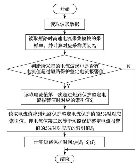
Figure 10 Flowchart of Short Circuit Current Limiting Time Calculation Subroutine
The overload protection time is the time interval from when the load current flowing through the protector exceeds the overload protection setting current alarm value to when the load current drops to 5% of its value. The subroutine process for calculating overload protection time is similar to the program for calculating short-circuit current limiting time, except that the sampling rate of the high-speed current acquisition module during overload is different from the setting during short-circuit.
5、 Ankerui Electric Fireproof Current Limiting Protector
5.1 Overview
The ASCP series electrical fire-resistant current limiting protector can effectively overcome the drawbacks of traditional circuit breakers, such as high short-circuit current, long operating time, large short-circuit arc, and short service life. When a short circuit fault occurs, it can quickly limit the short-circuit current at microsecond level to achieve arc extinguishing protection, thereby significantly reducing electrical fire accidents and ensuring the safety of personnel and property in the use area.
5.2 Functional Features
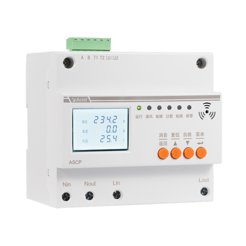
1) Short circuit current limiting: When a short circuit fault occurs in the circuit, it can achieve fast current limiting protection within 150us, in case of electrical fire accidents caused by excessive short circuit current.
2) Overload current limiting: When the current of the protected line exceeds the rated current, the line is overloaded and the overload duration exceeds the set time (3-60 seconds), the protector performs current limiting protection.
3) Over temperature current limiting: When the temperature of the internal components of the protector exceeds the set value, the product activates the over temperature current limiting protection function to prevent product damage caused by high temperature.
4) Overvoltage/undervoltage protection: When the protector detects a line voltage undervoltage or overvoltage, it emits an audible and visual alarm signal, and can pre-set whether to activate current limiting protection.
5) Cable temperature monitoring: When the monitored cable temperature exceeds the alarm set value, the protector emits an audible and visual alarm signal, and can pre-set whether to activate current limiting protection.
6) Leakage current monitoring: When the leakage of the monitored line exceeds the alarm set value, the protector emits an audible and visual alarm signal, and can pre-set whether to activate current limiting protection.
7) Communication function: It has 1 RS485 interface and 1 2G wireless communication, which can send data to the background monitoring system for remote monitoring. The monitoring backend can be the Acrel-6000/B electrical fire monitoring host, the Acrel-6000 security cloud platform, or a third-party monitoring software or platform.
5.3 Equipment selection
Application scenarios |
model |
product image |
Main functions |
It can be widely used for line protection at the end of various power plants such as schools, hospitals, shopping malls, hotels, entertainment venues, temples, cultural relics buildings, exhibitions, residences, warehouses, kindergartens, elderly buildings, collective dormitories, electric vehicle charging stations, rental shopping malls, wholesale markets, trade markets, and warehouses for Class A, B, and C dangerous goods. |
ASCP210-40D |
|
It can achieve functions such as short-circuit current limiting and arc extinguishing protection, overload current limiting protection, internal over temperature current limiting protection, over and under voltage protection, leakage monitoring, cable temperature monitoring, etc. It has 1 RS485 communication channel and 1 GPRS (or NB) wireless communication channel, with a rated current of 0-40A and a rated current menu that can be set. |
ASCP210-63D |
|
It can achieve functions such as short-circuit current limiting and arc extinguishing protection, overload current limiting protection, internal over temperature current limiting protection, over and under voltage protection, leakage monitoring, cable temperature monitoring, etc. It has 1 RS485 communication channel and 1 NB (or 4G) wireless communication channel, with a rated current of 0-63A and a rated current menu that can be set. |
|
ASCP310-63B |
|
Three phase current limiting protectors are mainly used for line protection in electric vehicle charging stations. It has short-circuit current limiting, overload current limiting, internal over temperature current limiting, over and under voltage, leakage monitoring, and cable temperature monitoring functions, with 1 RS485 communication, rated current of 63A, and can be set through the host menu. |
|
ASCP320-160B |
|
Three phase current limiting protectors are mainly used for line protection in electric vehicle charging stations. It has short-circuit current limiting, overload current limiting, internal over temperature current limiting, over and under voltage, leakage monitoring, and cable temperature monitoring functions, with 1 RS485 communication, rated current of 160-250A, and can be set through the host menu. |


6、 Conclusion
The electrical performance automatic testing device for electrical fire current limiting protectors based on LabVIEW developed in this article can achieve automatic testing of electrical performance for various specifications of electrical fire current limiting protectors such as 0-40A, 0-63A, 160-250A, etc. It can automatically capture short-circuit current limiting test waveforms and overload protection test waveforms, accurately calculate short-circuit current limiting time and overload protection time, and generate test reports. Tests have shown that the testing device has improved testing efficiency and safety performance, reduced testing costs, and achieved automation and intelligence in electrical performance testing.
[Reference]
Lu Qiwei, Ru Tao, Ye Zeyu, Cheng Jinpei, development of an automatic testing device for electrical performance of electrical fire protection and current limiting protectors;
Liu Yixiang, Tang Hao, Jin Jing, etc., Typical urban fire statistics based on cause analysis
Ankerui Safety Electricity Management Cloud Platform version 220.04;
Ankerui Enterprise Microgrid Design and Application Manual, June 2020 edition.