-
E-mail
jdyb8888@163.com
-
Phone
18015181778
-
Address
Gongyi Road, Jinhu Industrial Park, Jiangsu
Jiangsu; Jinhu Jindi Instrument Co., Ltd
Installation of Thermal Gas Mass Flow Meter
Date: 2021-02-26Read: 11
Selection of installation location
Choose a horizontal straight pipe section for installation. The requirements for the straight pipe sections before and after the installation point table are: the distance between the upstream throttling element and the installation point must be greater than 5 times the diameter of the pipeline, and the distance between the downstream throttling element and the installation point must be greater than 3 times the diameter of the pipeline. If conditions permit, we recommend making the straight pipe sections before and after the table as long as possible.
Base installation
According to different installation methods, the base can be divided into standard and simplified types. When installing, the base should be located at the top of the pipeline section direction, and the axis of the base through-hole should be perpendicular to the axis of the pipeline. Ideal base welding position and welding process.
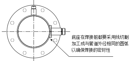
Before fastening the stainless steel valve to the base of the welded pipeline, a sealing gasket should be used on the pressure contact surface (nylon material should be used for medium temperatures below 100 ℃).
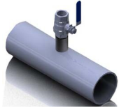 3、 Installation of Thermal Gas Mass Flow Meter
1. Loosen the stop nut on the instrument sensor connecting rod, so that the sensor storage chamber connecting nut can slide along the sensor connecting rod towards the sensor direction, and the sensor can be retracted into the sensor storage chamber connecting nut.
2. Tighten the sensor storage chamber connection nut onto the ball valve (a sealing gasket needs to be added between them before screwing in)
3. Open the ball valve and insert the sensor connecting rod into the pipeline until the retaining nut can be locked with the cavity connecting nut.
4. Rotate the sensor link to align the marked arrow with the direction of medium flow, and tighten the locking nut.
5. Change the direction of the converter. If the direction of the display screen cannot meet the requirements of the on-site display angle, the direction of the display screen can be changed, and the display head can rotate in six horizontal directions. Cut off the power, open the front cover of the converter, remove the connection between the sensor and the converter. The wiring positions of the 4 groups of 6 wires are arranged from left to right as [two red wires per group], [one red wire per group], [one yellow wire per group], and [two yellow wires per group]. We have already divided the groups at the factory. Loosen the flange of the meter head (unscrew 6 M6 hexagon socket screws), and slowly move the meter head (be careful not to drop the meter head). When it is convenient to observe, re fix the flange and connect the sensor and converter wires. Close the front cover tightly and connect the power supply.
6. If you are installing this instrument horizontally, the display screen can be flexibly installed at 90 ° 180 ° 270 ° to meet your actual on-site needs.
Last Article: Application scope of orifice flowmeter
Next Article: The Development Trend of Instrumentation Products in China