-
E-mail
li.fu@perkinelmer.com
- Phone
-
Address
1670 Zhangheng Road, Pudong New Area
PerkinElmer Enterprise Management (Shanghai) Co., Ltd
Application of TMA 4000 in Measuring the Thermal Expansion Coefficient of Electronic Circuit Boards
Date: 2025-10-16Read: 4
Background:
Dimensional mismatch caused by thermal expansion is one of the main causes of damage to electronic circuit boards. To avoid this situation, high thermal conductivity materials are usually used for heat dissipation, and low expansion materials are used in combination with low expansion silicon wafers and ceramic insulators. Thermomechanical analysis (TMA) has long been used to measure the coefficient of thermal expansion (CTE) of circuit boards, electronic components, and other constituent materials. There are mature and reliable standard testing methods for the temperature inflection points of glass transition temperature, thermal expansion coefficient changes, sample softening, and stress release effects. For layered composite products, TMA's corresponding testing method can evaluate the time required for the destruction of the material's regular layered structure during the heating process. The design of TMA 4000 greatly simplifies the above testing process and is very suitable for measuring the expansion of small devices with low expansion rates. This article provides some test cases of these standard methods.
TMA 4000 experimental section:
The following standard TMA testing procedures are used for data testing:
·Nitrogen purging;
·Heating rate of 5 or 10 ℃/min;
·Control the temperature of the furnace cooling tank at 15 ℃ by circulating cooling water.
Test results:
Z-axis thermal expansion coefficient of 0.33mm thick PC board:
The test signal for the coefficient of thermal expansion (CTE) is directly proportional to the height of the analyzed sample, so measuring the expansion of a sample with a height of only 0.33 millimeters requires high sensitivity to TMA. IPC-TM-650 2.4.247- "Measurement of Glass Transition Temperature and Z-axis Thermal Expansion with TMA" was used as standard 1 in the experiment. This standard method requires that the height of multi-layer composite circuit board samples should be at least 0.5 millimeters. Cut a small piece from one corner of the multi-layer PCB circuit board as the test sample (Figure 1), and measure it in the X, Y, and Z axis directions using a micrometer. Due to the stacking of two layers in the Z-axis direction, the sample height reaches 0.66 millimeters. The sample is placed on a small sapphire base, and a flat probe is used to apply a small force to the sample. This not only eliminates the error caused by sample deformation caused by the probe, but also eliminates the step of preprocessing the sample (see Figure 1, deducting the baseline to eliminate the influence of the base).
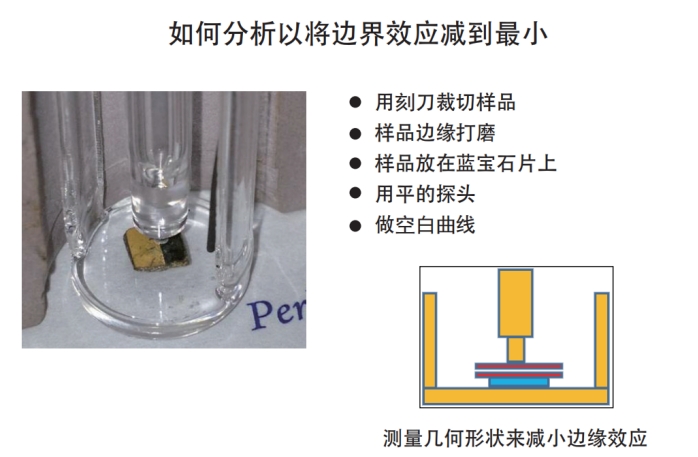
Figure 1. Geometric shape of the sample
Normally, only one heating is performed and the glass transition temperature is obtained through displacement curves; If there are special requirements, the sample needs to be subjected to secondary heating, and the thermal expansion coefficients on both sides of the glass transition can be obtained from the curve of the secondary heating. Generally speaking, the glass transition temperature is the starting point of molecular motion associated with a decrease in modulus and an increase in coefficient of thermal expansion (CTE). The glass transition temperature Tg obtained from TMA is the intersection of the extrapolated lines of expansion data above and below this region. As shown in Figure 2.
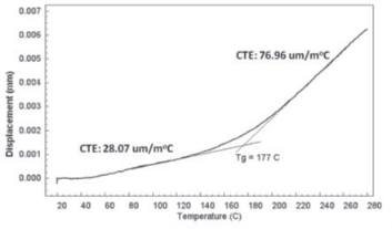
Figure 2. Analysis of Z-axis direction of PC chip
Explosion time:
The testing on the Z-axis dimension of this sample was conducted in accordance with IPC-TM-650 clause 2.4.24.1, namely the layering time testing method 1 experiment. In this experiment, the sample shown in Figure 1 was heated to 265 ℃ and then subjected to isothermal treatment until the sample structure was destroyed (commonly known as "explosion plate"). The data is shown in Figure 3.
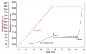
Figure 3. Time test for layer structure failure ("bursting board")
Thermal expansion coefficient of 0.33mm thick PC board in XY axis:
The expansion test of PC chips in the XY plane also uses the IPC experimental method: 2.4.41 Linear thermal expansion coefficient of electronic insulation materials. This method is based on ASTM method D696 and is suitable for small-sized sample 1. Similarly, the sample has not undergone any chemical cleaning or etching treatment before analysis. Testing in expansion mode does not require baseline deduction. The analysis results of the thermal expansion coefficient CTE and glass transition Tg in the XY plane are shown in Figure 4. The indistinct glass transition zone indicates that the glass fiber filler (also coated) effectively suppresses the expansion of the circuit board.
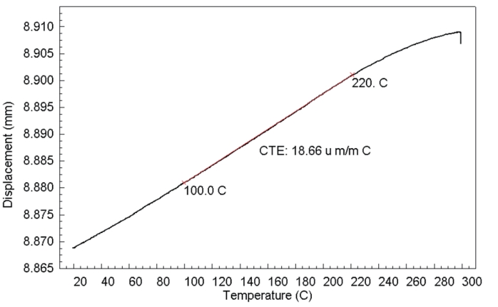
Figure 4. Expansion of PC chip in XY axis direction
Polyimide flexible circuit substrate:
Polyimide (PI) is a high-temperature resistant plastic that can be used for flexible connections between circuit boards. Conductive pathways can be printed on it, which is not prone to performance degradation, and the high glass transition temperature means that the material is dimensionally stable over a wide temperature range. The standard method used in this experiment is IPC-TM-650 2.4.24.5 for glass transition temperature and thermal expansion of high-density interconnect (HDI) and micro blind hole materials - TMA method 1.
Cut the thin strip of polyimide film sample with a blade along the longitudinal and transverse directions, with a thickness of 30 microns. Special sample fixtures are used to ensure that the samples are flat and without wrinkles, and each sample is analyzed in a tensile mode (the geometric shape of the sample is similar to Figure 5).
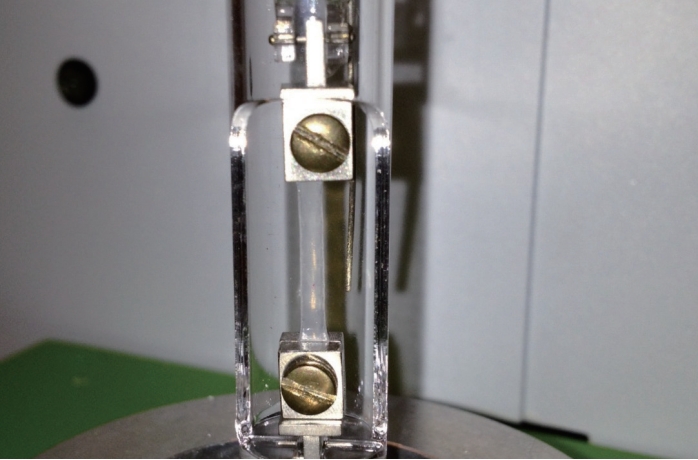
Figure 5. Film sample installed in stretching mode
The sample is heated repeatedly to ensure stable thermal state. The analysis results are shown in Figure 6. Before testing CTE, the baseline has been deducted to eliminate the expansion effect of the sample fixture (the baseline comes from the test results of quartz samples with the same expansion coefficient as the furnace material).
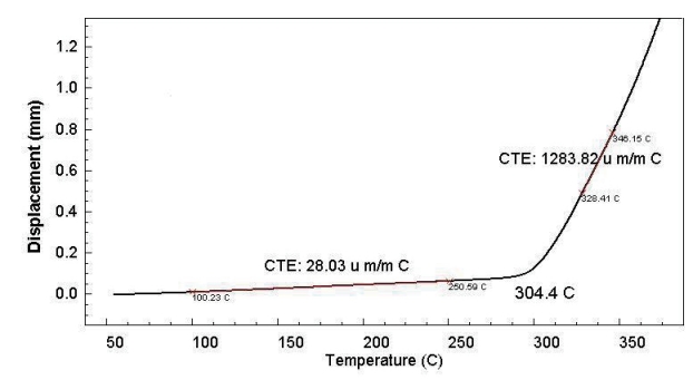
Figure 6. Longitudinal thermal expansion coefficient and glass transition of polyimide film
Figure 7 shows the data of polyimide tested under the same experimental conditions, but the sample analyzed this time was cut from a direction perpendicular to the longitudinal direction.
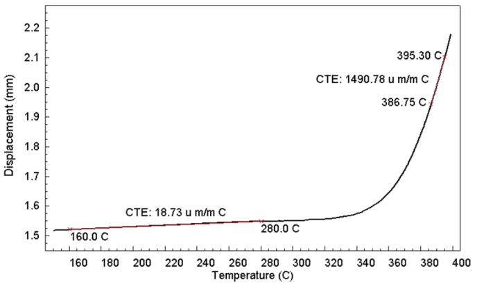
Figure 7. Thermal expansion coefficient of polyimide film in the cross-sectional direction
The difficult samples in the electronics industry were analyzed using TMA 4000 and corresponding standard methods, and the results showed that TMA 4000 can be used for simple and accurate measurements. The technology used in TMA 4000 provides proven sensitivity, reliability, and low maintenance costs.
References:
1. IPC-TM-650 Test Methods Manual, Institute of Electronic Circuit Interconnection and Packaging, 2215 Sanders Road, Northbrook, Illinois 60062-6135.