-
E-mail
2801283106@qq.com
-
Phone
15821569256
-
Address
No. 121, Building 2, No. 655 Gaoji Road, Sijing Town, Songjiang District, Shanghai
Download
Shanghai Shirun Industrial Co., Ltd
Structural characteristics of internal micrometer
Date: 2025-12-01Read: 10
Structural characteristics of internal micrometer
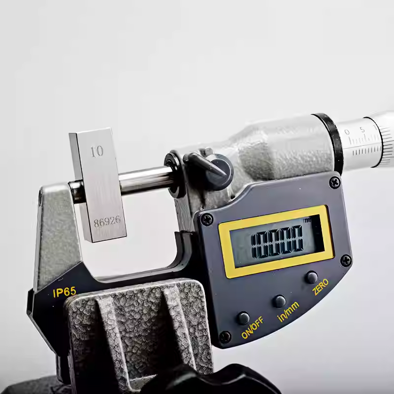
inside micrometerThe measurement lower limit of the micrometer is 50mm, 75mm, 150mm, etc., and the measurement upper limit is up to 5000mm. The indication range of a single internal micrometer is 25mm. It mainly consists of a fixed measuring head, nut, fixed sleeve, locking device, micrometer screw, differential cylinder, movable measuring head, adjusting measuring tool, pipe joint, spring, sleeve, and measuring rod. It is mainly used for measuring internal dimensions and often requires the use of extension rods. Different combinations of micrometer heads and extension rods can obtain different measurement ranges, usually 50-5000mm
The internal diameter micrometers produced by Nok can be divided into ordinary internal diameter micrometers and rod type internal diameter micrometers. The former is also known as the internal diameter micrometer with measuring claws, also known as the Nok measuring micrometer, which is suitable for measuring small hole diameters. The difference between this Nok micrometer and the external diameter micrometer is that the direction of the engraved line on the fixed sleeve is exactly opposite. This is because when the differential cylinder rotates, the measuring rod drives the left measuring claw to move.
When measuring large apertures, a rod type internal micrometer or an extension rod can be used. The Nok internal micrometer is composed of a differential head and a complete set of extension rods, equipped with an adjustment gauge (or calibration caliper) with two parallel measuring surfaces, used to calibrate the zero position of the differential head.
The structural characteristic of the differential head is the absence of a force control mechanism, so the measurement error caused by force measurement will correspondingly increase. There are threads on one end of the fixed sleeve for connecting the rod. There is a locking nut that compresses the end face of the differential cylinder and the flange at the tail of the micrometer screw, so that the Nok micrometer screw and the differential cylinder are integrated.
Precautions for use:
1. Choose extension rods and select the minimum number of extension rods as much as possible to form the required dimensions between them, in order to reduce cumulative errors. When connecting extension rods, they should be arranged according to size, and larger extension rods should be connected to differential heads. If the small-sized extension rod is arranged in the middle of the assembly, the axis of the micrometer after extension will increase in bending due to the accumulation of parallelism errors on the end face of the pipe head, resulting in an increase in measurement error.
2. Before use, use a calibration caliper to calibrate the zero position of the differential head,
3. When using a Knock internal micrometer with a measurement lower limit of 75 (or 150) millimeters, the curvature radius of the measured surface must not be less than 25 (or 60) millimeters, otherwise it may be measured by the edge of the measuring head sphere of the internal micrometer.
4. Measurement must pay attention to the influence of temperature to prevent heat transfer by hands or other heat sources, especially for large-sized internal micrometers that are significantly affected by temperature changes. Before measurement, it should be strictly isothermal and the measurement time should be minimized as much as possible.
5. When measuring, the fixed measuring head is in contact with the measured surface. While swinging the movable measuring head, rotate the differential cylinder to make the movable measuring head touch the measured workpiece in the correct position, and then read from the inside micrometer. The so-called correct position refers to the minimum value that should be measured when measuring the distance between two parallel planes; Measure the inner diameter size, find the minimum value in the axial direction, and find the maximum value in the radial direction. Before leaving the workpiece for reading, use a locking device to tighten the micrometer screw before taking the reading.
6. Extension principle: The longest extension rod is connected to the differential head chain, the shortest is connected to the fixed measuring head, and the middle extension rod is arranged in order of size and length. If the extension rod with a smaller Nock size is not arranged in the middle of the combination according to the above connection, the axis of the extended micrometer will bend due to the accumulation of parallelism error of the pipe head, resulting in an increase in measurement error. At the same time, if the connection is not made according to the above regulations, it will be inconsistent with the state of verifying its specifications, causing measurement errors
Structural characteristics of internal micrometer