-
E-mail
sute@56412027.com
-
Phone
13818304481,13818304482
-
Address
No. 357, Lane 1080, Fuchang Road, Baoshan District, Shanghai
Shanghai Xuji Electric Co., Ltd
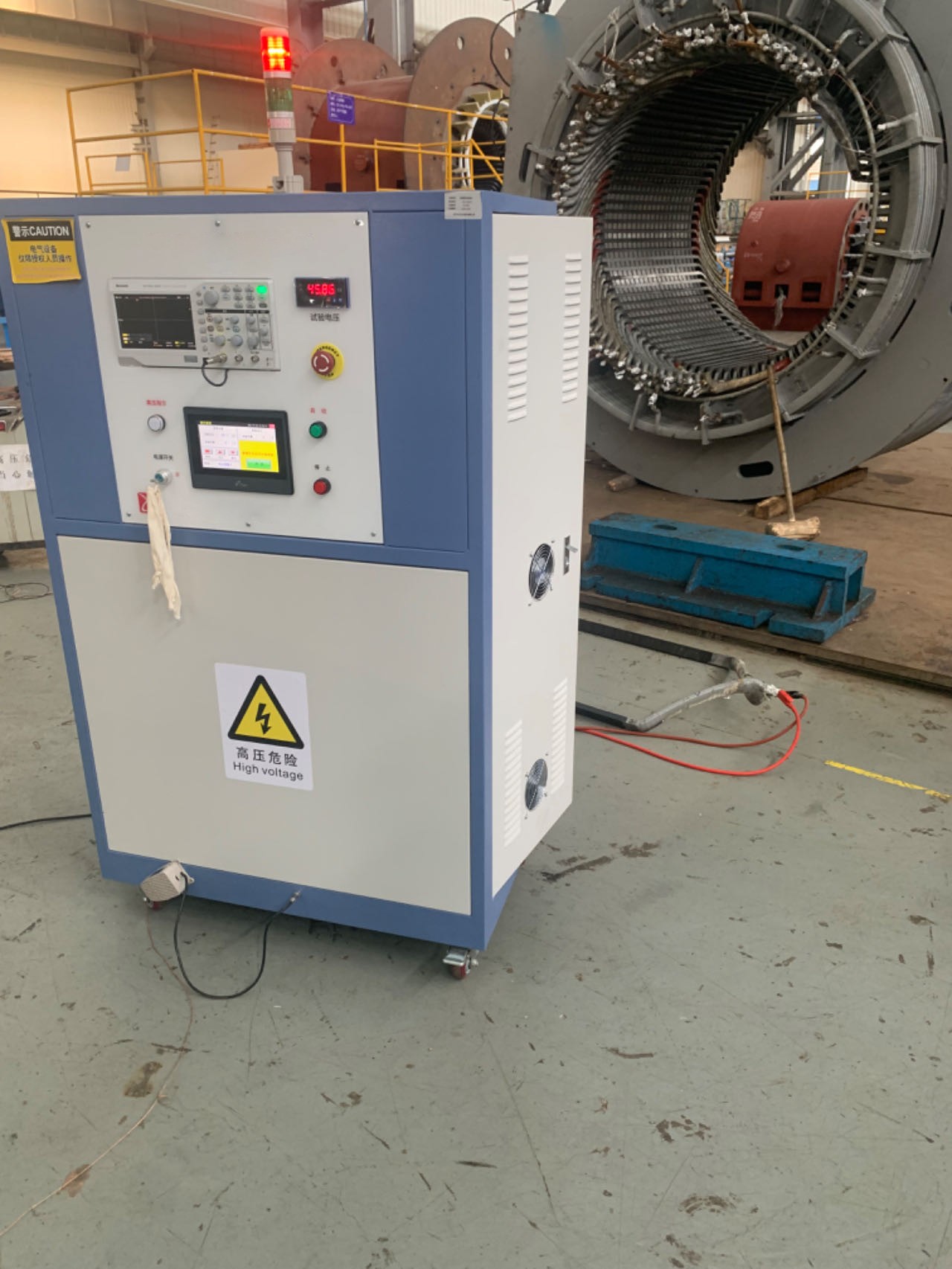
RZJ-40 interturn impact withstand voltage tester
Date: 2025-08-22Read: 69
general narrate, recount, state
The interturn impulse withstand voltage tester adopts the pulse waveform comparison method,A testing instrument that simulates the detection of overvoltage in two coils or windings using high-voltage shock waves, and uses an oscilloscope to distinguish the waveform differences between the two windings. It can not only quickly and accurately diagnose various faults such as insulation corona discharge between coils or windings, local or phase to phase short circuits, open circuits, wiring errors, coil balance, etc., but has also been widely used in related industries.
RZJ - 40Interturn impact withstand voltage testerSuitable for rated voltage 10000VInsulation testing of windings between turns for large, medium, high voltage, AC, and DC motors of different sizes; It can also be used for inter turn insulation detection of transformer windings and electrical coil windings. Due to the inconsistent insulation structure and insulation materials of motor and transformer windings, especially the different levels of operator craftsmanship, insulation damage can occur to varying degrees in processes such as winding, wire embedding, wire scraping, joint end shaping, and handling, resulting in various forms of inter turn insulation faults in the windings. Therefore, inter turn insulation is a weak link in motors and transformers.
RZJ - 40 Interturn impact withstand voltage testerThe basic principle is to detect the symmetrical balance of the impedance of the test sample,Non destructive simulation test of equivalent overvoltage on motor and transformer windings using shock wave comparison method with high-frequency and high-voltage pulses,By using the oscilloscope of the instrument itself to observe and compare waveforms, it is possible to intuitively, quickly, and correctly test winding turn to turn short circuits and various impedance imbalance faults.
technical indicators
● Wavefront time:0.2µs
● Polarity: Negative polarity
● Pulse peak voltage: 2.0 ~≥40kV(Continuously adjustable)
● Peak voltage meter display:040kV ±5%
Pulse energy storage capacitor: 0.03 ~ 0.05µF ± 10%
●output energy : 40 J
●dischargefrequency : The discharge frequency is1time/second
●number of discharges : 1-9Next arbitrary setting (standard requirement is5Next time)
●Insulation resistance: The insulation resistance of the power input terminal to the rack is greater than or equal to50MOhm;
●Dielectric strength: The power input end can withstand the rack1500V/50Hz 1minVoltage endurance test, no flying fox, no breakdown phenomenon;
The instrument is equipped with a digital storage oscilloscope, which can save waveforms and print them on a computer.
● Dimensions (width, height, depth):700×1400×700(mm)(Width, height, depth)
● Weight:125 kg
● Instrument usage environment:
■ Power supply voltage:220V+10%;50Hz/60Hz+2%;
■Ambient temperature0 ~ 40Degree; Relative humidity: not greater than80%;
■ Working power supply: ~220V±5 % 50Hz
■ merit consume : 2000 VA
●Scope of application:rated voltage 13800VAC/DC motor coils and overall inter turn insulation withstand voltage test.
pretend box single
RZJ - 40Interturn impact withstand voltage tester |
One Taiwan |
high pressurewarning light |
One only |
TBS 1072Bdigital storage oscilloscope(built-in) |
One Taiwan |
High voltage testing line |
two root |
~ 220Vpower cord |
One root |
Probe signal line |
One root |
Instrument User Manual |
One copy |
foot switch |
One only |
Instrument Qualification Certificate |
One copy |
Instrument Warranty Card |
One copy |
Instrument Test Report |
One copy |
Instrument packing list |
One copy |
Precautions
This instrument is a high-voltage tester, and during testing, onefixedAttention should be paid to personal safety. After the instrument is turned on (when the warning light is on), attention should be paid to safety. inHigh Voltage IndicationWhen the light is on (Figure 2), do not touch the high-voltage output terminal, output lead clamp, and the tested winding (motor) to avoid electric shock.
The power supply of the instrument must be reliably grounded, and high-voltage testing is strictly prohibited without a grounding wire. Because the high voltage of thousands of volts can cause the casing to carry high voltage, endangering personal safety and damaging the low-voltage control circuit, the grounding output terminal of the instrument is located in the lower left corner of the back of the instrument and needs to be connected to the grounding wire with copper wire.
When the instrument malfunctions and needs maintenance, it should be carried out by professional personnel. When opening the box for maintenance, the high-voltage capacitor should be discharged with a grounding wire before proceeding to avoid electric shock.
Last Article: CF-4 Clamping Force Tester
Next Article: RZJ-30 interturn impact withstand voltage tester