-
E-mail
sallen@sure365.com.cn
-
Phone
13821593578
-
Address
Building 1-10, Huading New Area, Haitai Innovation 6th Road, Huayuan Industrial Zone (Outer Ring Road), Xiqing District, Tianjin City
Download
Tianjin Xun'er Technology Co., Ltd
LUX series spiral vortex flowmeter product description
Date: 2025-12-13Read: 14
I. Overview
The flow profile of a flow sensor is similar to the profile of a Venturi tube, with a set of spiral guide vanes placed on the inlet side. When the fluid enters the flow sensor, the guide vanes force the fluid to generate intense vortex flow. When the fluid enters the diffusion section, the vortex flow is subjected to backflow and begins to undergo secondary rotation, forming a gyroscopic vortex precession phenomenon. The precession frequency is directly proportional to the flow rate and is not affected by the physical properties and density of the fluid. By measuring the secondary rotation precession frequency of the fluid with the detection element, good linearity can be obtained over a wide range of flow rates. The signal is amplified, filtered, and shaped by a preamplifier into a pulse signal proportional to the flow rate, and then sent to the microprocessor for integration processing along with temperature, pressure, and other detection signals. Finally, the measurement results are displayed on the LCD screen(Instantaneous flow rate, cumulative flow rate, temperature, and pressure data).
2、 Product Features
Multiple physical parameter alarm output, which can be selected by the user as one of them;
No mechanical movable parts, not easily corroded, stable and reliable, long service life, long-term operation without special maintenance;
The intelligent flowmeter integrates a flow probe, microprocessor, pressure, and temperature sensors, and adopts a built-in combination to make the structure more compact. It can directly measure the flow rate, pressure, and temperature of the fluid, and automatically track compensation and compression factor correction in real time;
The use of dual detection technology can effectively improve the strength of detection signals and suppress interference caused by pipeline vibration;
adoptDomestic advancedThe intelligent anti vibration technology effectively suppresses interference signals caused by vibration and pressure fluctuations;
Adopting a Chinese character dot matrix display screen with multiple digits, the reading is intuitive and convenient. It can directly display the volume flow rate under working conditions, the volume flow rate under standard conditions, the total amount, as well as parameters such as medium pressure and temperature;
The flowmeter head can be360Rotating degrees, easy to install and use.
3、 Structure and Working Principle
3.1 Flow meter structure (see figure)3-1)
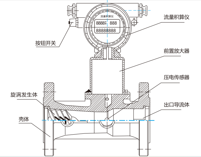
Figure 3-1 Flow Meter Structure
3.2 working principle
When the fluid along the axial direction enters the inlet of the flowmeter, the rotating blades force the fluid to undergo rotational motion, thus generating a vortex flow at the center of the vortex generator. The vortex flow spirals in the Venturi tube and suddenly throttles at the contraction section, accelerating the vortex flow. When the vortex suddenly enters the diffusion section, it is forced to undergo a second rotation in a spiral manner due to the reflux effect. If the instrument has the most optimized geometric structure inside, then the frequency of the vortex is proportional to the flow rate over a wide range and is linear. This frequency is a weak electrical signal detected by an electrical sensor, which is amplified, filtered, and shaped by a preamplifier to be converted into a pulse signal proportional to the flow rate, and finally sent to a flow integrator for operation and processing.
Working principle of flow integratorThe principle block diagram of the integrator is shown in the figure3-2As shown, it includes a high-performance low-power processor,LEDThe LCD screen, its driving circuit, and peripheral circuit are composed of a microprocessor that receives pulse signals from a preamplifier and passes them throughCPUCalculate and process, obtain instantaneous flow rate and cumulative flow rate values respectively, and save them to memory. The flowmeter uses four function buttons: reset(RST)Keys, settings(SET)Key+1(INC)Keys and Shifts(SHT)Key, save relevant parameters to memoryEEPROMIn the middle.
The microprocessor continuously detects the battery voltage value. Once the battery voltage falls below the preset voltage thresholdLCDUpper battery identifier“[Battery icon]”Flashing phenomenon occurs to remind users to replace the battery. Flow signal output, a pulse signal, is output to the driver amplification circuit through a gate controlled by a microprocessor, amplified and transmitted to the user's computer, or throughD/AandV-IConvert to4~20mAThe current signal is then transmitted to the user's computer; can also be throughRS485Implement data communication between the interface and the upper computer.

Figure 3-2 Schematic diagram of flow integrator
3.3 The flowmeter displays the volumetric flow rate in the group state. If it needs to be converted to the volumetric flow rate in the standard state, please calculate according to the following formula:

Where:
Qn—Volume flow rate under standard conditions(m3/h)
Qs—The displayed value of the flowmeter(m3/h)
Pa—standard atmospheric pressure(101.325kPa)
Tn—Absolute temperature under standard conditions293.15K(20℃)
Tg—Absolute temperature under working conditions(273.15+t)K
Pg—Pipeline pressure under working conditions(gauge pressure(KPa)
Pn—local atmospheric pressure(kPa)
3.4 Pressure loss of flowmeter
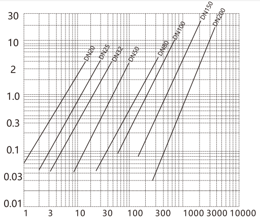
Under standard conditions, when the medium is dry air, the pressure loss of various specifications of flow meters△P0According to the diagram11find out(The maximum value is shown in the table1)
The pressure loss of a flowmeter can be calculated according to the following formula for different media in different states:
△ P=P/1.025⋅ △P0
Where:
△P—Actual pressure loss of flowmeter(kPa)
P—The density of the medium in its actual state(kg/m3)
△P0—Under standard conditions, the pressure loss of the flowmeter when the medium is dry air(kPa)