-
E-mail
75046748@qq.com
-
Phone
17317784455
-
Address
Room 508, Lane 133, Shengang Avenue, Lingang New Area, China (Shanghai) Pilot Free Trade Zone
Product Categories
- Online monitoring system
- High purity germanium (HPGe) radiation detector
- Micro Detective HX Advanced Handheld Radiation Detection and Identification RIID
- Multi channel analyzer
- Delay, gates and delay generators, logic modules and linear gates
- Time amplitude converter and calibrator
- DataMaster Spectral File Format Converter
- Silicon charged particle radiation detector
Jiarui (Shanghai) Technology Co., Ltd

566 time amplitude converter
NegotiableUpdate on 11/20
- Model
- Nature of the Manufacturer
- Producers
- Product Category
- Place of Origin
Overview
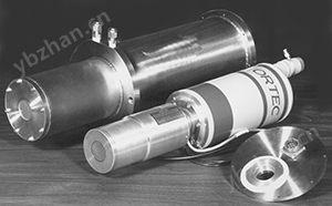
Suitable for time spectrum analysis within the range of 10ns to 2ms. Effective start and effective conversion output can be selected. Delay and width output can be synchronized with stop or external gating signals. Unnecessary start input signals can be rejected. Positive and negative input signals. ORTEC566 Time Amplitude Converter (TAC) can measure the time interval between start and stop input pulses
Product Details

- Suitable for time spectrum analysis within the range of 10 ns to 2 ms
- Effective startup and effective conversion output
- Optional output delay and width
- Synchronize output with stop or external gating signals
- Reject unwanted startup input signals
- Positive and negative input signals
The ORTEC 566 Time Amplitude Converter (TAC) can measure the time interval between the start and stop input pulses and generate analog output pulses proportional to the measurement time. It can be used to perform timed experiments that require a time range of 10 ns to 2 ms, allowing experimenters to flexibly analyze random events that occur within a selected time range. Provide a time range of 50 ns to 2 ms through the front panel controls.
-
data+
-
 566 brochure
- 566 brochure (A4)
- 566 Handbook
-
-
More information+
The starting input of the 566 type can be disabled by the pulse or DC level on the rear panel door input connector.
Provide effective start and effective transition outputs for each accepted start and stop input. The duration of effective startup output represents the time interval from the received startup to the end of the reset. The effective conversion output occurs between the end of the internal delay after stopping and the end of the reset.
The selectable TAC output width and variable delay (easily adjustable) increase the flexibility of the 566 instrument, making it easy to adapt to various time spectrum systems. The output of TAC can be synchronized with the stop signal or external gate signal, further enhancing its versatility.
The 566 model adopts DC coupling and gate control, so the input count rate will not be paralyzed or otherwise hinder normal operation. The TAC output should be connected to the DC coupling input of the multi-channel analyzer to achieve high counting rate performance.
-
Specifications+
performance
temporal resolution
For all ranges,FWHM≤ Full scale0.01%Plus5 ps.
Temperature instability
≤±0.01%/°C(±100 ppm/°C), full range or ±10 ps/°C(whichever is larger),0to50°C.
Differential nonlinearity
usually<1%, from10 nsOr at full scale2%(whichever is larger) to100%.
Integral nonlinearity
≤±0.1%From10 nsOr at full scale2%(whichever is larger) to100%.
Reset cycle
ForX1andX10Multiple, fixed at1.0 MsForX100Multiple, fixed at5 MsForX1KandX10KMultiple, fixed at50 MsIt occurs after exceeding the range, gating cycle, or external gating reset cycle.
Start to Stop
Convert timeMinimum ≤5 ns.
Input count rate
>30 MHz.
control(Front panel)Scope(ns)
The three position rotary switch can be selected between the received start and stop input signals50、100or200 nsThe full-scale time interval.
multiple
The five position rotary switch can be operated through1、10、100The1Kor10KMultiplying factors to expand the time range.
Delay(µs)
20The adjustable potentiometer with a screwdriver can turnTACThe delay of the output is relative to the reception of the stop input signal0.5 Mschange to10.5 MsOnly available inIntOperate in select mode.
Selective mode
The dual lock toggle switch allows for the selection of internal or external sources and is used to initiate the gating cycle for selecting fromTACOutput selected valid information.
control(Rear panel)Door mode
The dual lock toggle switch can select the matching or anti matching operation mode for the starting circuit. During the interval of the gate input signal, the startup circuit is activatedCoincLocation enabled or inAntiLocation is disabled.
Log Curr
Dual lock toggle switch can be selected to use ±6 VOr ±12 VThe power cord of the power box is used to provide current for the internal logic circuit.
Within ±6 VLocation, when usedNIMstandardVWhen using a power source,566Type in a singleNIMWithin the current distribution range of the width. Within ±12 VLocation, for+12 Vand-12 VPower box power cord,566More than a single typeNIMThe current distribution range of the width. However, at that location566Type can or cannot be provided+6 Vand-6 VCombined use of power supply.
input terminalAll four input terminals listed below are DC coupled, edge triggered, and can be selected from printed circuit boards(PWB)Jumper to accept negative or positiveNIMStandard signal. When the input impedance is in the negative position, it is50 Ω, when in the positive position>1 kΩ. The nominal threshold is at the negative position-400 mVWhen in the correct position, it is+2 V.
Selected through
front panelBNCThe connector provides a way toExtSelect mode fromTACExternal methods for selecting effective output signals. After stopping inputExtInput signals exceeding the threshold within the reset interval will activate the linear gateTACThe read cycle of the output. The factory setting is in the positive input position.ExtThe minimum value of the gate reset interval is approximately0.5 MsThe nominal value is10 Ms.
start
When the startup input signal exceeds the threshold, the front panelBNCThe connector will start time conversion. The factory setting is in the negative input position.
停止
When the stop input signal exceeds the threshold, the front panelBNCThe connector will terminate the time conversion. The factory setting is in the negative input position.
door
rear panelBNCThe connector provides an external method for selecting the startup circuit when it matches or contradicts the startup input signal. The gate input signal must cross the threshold ≥ before starting the input signal10 nsAnd it must overlap with the triggering edge of the startup input signal. The factory setting is in the positive input position.
Output terminalTACoutput
front panelBNCThe connector provides unipolar pulses.
- amplitude0 Vto+10 V, with startup/The time difference for stopping input is proportional.
- time atIntThe delay period in select mode ends; atExtTimely gating input in gating mode.
-
width can pass throughPWBPotentiometer from ≤1 MsTo ≥3 MsMake adjustments.
impedanceZo<1Oh.
-
rise time~250 ns.
fall time~250 ns.
VAL ST
rear panelBNCConnectors providedNIMStandard slow positive logic level signal.
- amplitude nominal+5 V. can be done throughPWBJumper selection compensation signal.
- Time and width From the received startup input to the end of the reset.
- impedanceZo<10Oh.
- rise time ≤50 ns.
- fall time ≤50 ns.
effectiveConv
Rear panel connector providedNIMStandard slow positive logic level signal to indicate effective conversion.
- amplitude nominal+5 V. can be done throughPWBJumper selection compensation signal.
- Time and width From the end of internal delay after stopping to the end of reset.
- impedanceZo<10Oh.
- rise time ≤50 ns.
- fall time ≤50 ns.
Electrical and MechanicalRequired power supply
Logic current switch
- ±6 V: +24 V, 45 mA; +12 V, 95 mA; +6 V, 140 mA;–24 V, 50 mA;–12 V, 140 mA;–6 V, 300 mA.
- ±12 V: +24 V, 45 mA; +12 V, 210 mA; -24 V, 50 mA;–12 V, 405 mA.
weight
Net weight 1.5Kilogram(3.3Pound).Shipping weight 3.0Kilogram(7Pound).
size
NIMStandard single width module,3.43 x 22.13Centimeters(1.35 x 8.714Inches), compliantDOE/ER-0457TThe requirements.
-
Order Information+
model
description
566
Time amplitude converter
Similar Product Recommend