-
E-mail
75046748@qq.com
-
Phone
17317784455
-
Address
Room 508, Lane 133, Shengang Avenue, Lingang New Area, China (Shanghai) Pilot Free Trade Zone
Product Categories
- Online monitoring system
- High purity germanium (HPGe) radiation detector
- Micro Detective HX Advanced Handheld Radiation Detection and Identification RIID
- Multi channel analyzer
- Delay, gates and delay generators, logic modules and linear gates
- Time amplitude converter and calibrator
- DataMaster Spectral File Format Converter
- Silicon charged particle radiation detector
Jiarui (Shanghai) Technology Co., Ltd
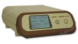
DSPEC LF digital signal processing gamma ray spectrometer
NegotiableUpdate on 11/20
- Model
- Nature of the Manufacturer
- Producers
- Product Category
- Place of Origin
Overview
The fully functional digital spectrometer for HPGe and NaI detectors is automatically optimized to achieve detector performance. ORTECSMART-1 intelligent HPGe supports continuous display of detector status and health status information, real-time spectrum display, fast data transmission, and easy installation
Product Details

- Fully functional digital spectrometer for HPGe and NaI detectors
- Automatic optimization to achieve detector performance ()
- ORTEC SMART-1 ™ Intelligent HPGe support
- Continuously display detector status and "health status" information
- Fast data transmission for real-time spectral display
- Easy to install, true USB 2.0 plug and play
- Excellent temperature and counting rate stability
- Including MAESTRO MCA simulation software
- Each function can be controlled by a computer
DSPEC LF is an ORTEC DSPEC USB series digital technology gamma ray spectrometer. It has spectral stability against changes in temperature and counting rate, while retaining multiple advantages of the other two models. Many environmental and radiochemical laboratories have found that this instrument is used for MCA in laboratory HPGe or NaI detector systems for daily sample counting.
-
data+
-
 DSPEC LF brochure
- DSPEC LF brochure (A4)
- DSPEC LF Manual
-
-
More information+

SMART-1 ™ Support Quality Data - Consistently Consistent
ORTEC's SMART-1 detector is very intelligent. They monitor and store the "health status" of the detector (detector temperature, preamplifier power, bias over range, bias on/off status). The single inspection of DSPEC LF will verify whether the detector is ready and ready for acquisition. During the collection process, the SMART-1 detector continuously monitors the State of Health (SOH) to ensure the integrity of the collected data. At the end of the collection, the SOH marker in the SMART-1 detector will be quickly checked, and then displayed whether there are any parameters deviating from the specification during the measurement period. This is crucial for environmental samples that require long-term counting and regulatory samples that require data integrity.Another major advantage is that the SMART-1 detector is pre-set with recommended bias values at the factory. You no longer need to check the manual or label on the detector to set the correct bias value. As long as DSPEC LF is turned on, the SMART-1 detector will automatically detect the detector temperature, determine the correct high voltage bias, and turn it on.
Fast PC interface
DSPEC LF can be controlled at high speed through standard USB. The plug and play function makes installation easier. By using a USB hub, it is possible to simultaneously connect almost unlimited numbers of DSPEC LF. As an instrument compatible with ORTEC CONNECTONS, DSPEC LF can operate in both network and standalone configurations. ORTEC Connections refers to any hardware or software that can be seamlessly controlled and has built-in security anywhere in the laboratory.Convenient single cable connection with the detector
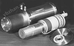
The ORTEC DIM (Detector Interface Module) used by DSPEC LF is connected to the detector using only one cable. DIM provides bias voltage close to the detector to carry only signals and low voltage power in the cable. Eliminating high voltage bias and the associated long-distance hazards.Monitoring important values
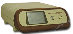
DSPEC LF displays the required values on the front panel LCD screen. DSPEC LF will display the instrument ID, name, serial number, pre design condition, current active and real time, dead time percentage, input count rate, HV status and value, as well as the serial number of SMART-1 detector.petite
The footprint of DSPEC LF is smaller than a piece of paper. Lightweight and sturdy multiple DSPEC LFs can be stacked together through their interlocking shells, without worrying about sliding or tilting.Combine with existing MCBs at will
ORTEC Connections software supports connecting to any combination and number of USB devices on any computer. For example, two digiDART can be connected to the same PC together with two DSPEC LFs using a USB hub. Any number of other ORTEC MCBs can be connected to the same system through network, printer ports, RS-232, or dual port memory. -
Specifications+
display
240 x 160Pixel backlightLCDProvide status information and instrumentsIDBias voltage information, active time, and real time.
number of concurrent connections
Supported by computers and softwareUSBLimitations of the hub. On each computerORTEC CONNECTIONSThe software supports at most127ThroughUSBConnected devices.
System gain setting
• Coarse gain adjustment:1、2、4、8、16or32.
•Fine tuning gain:0.45to1.
•The available gain setting range supports all types ofHPGeDetector. Specifically, using standardsOrtecThe preamplifier (gain to minimum gain) can achieve the following energy values:COAX
187 keVto12 MeV
LO-AX
94 keVto6 MeV
GLP/SLP
16.5 keVto1 MeV
preamplifier
Computers can choose to use it as a resistive preamplifier orTRPPre amplifier.
System conversion gain
The system conversion gain can be determined by software512to16kControl between channels.
Digital filter shaping time constant
•Rise time:0.8 Msto23 MsThe step size is0.2 Ms.
• flat roof:0.3to2.4The step size is0.1 Ms.Dead time correction
according toGedcke-HaleMethod for extended live time correction.
precision
The peak value of the reference area is at every second0to50,000Changes within the counting range<±3%.
linear
•Integral nonlinearity: using mixed sources(55Fe @ 5.9keVto88Y @ 1836keV)Measurement, before the spectrum99.5%<±0.025%.
•Differential nonlinearity: before the range99%<±1%(Using)BNCPulse generator and ramp generator measurement).
•Digital stabilizer: Controlled by a computer to stabilize gain and.System temperature coefficient
•Gain:<50 ppm/°C.[usually<30 ppm/°C.]
•Offset:<Full range3 ppm/°CThe rise and fall times are12 MsThe flat top is1 Ms. (Similar to simulation)6 MsPlastic surgery. )System processing capacity
>100,000 cps.
Pulse Stacking Rejecter
Automatically set threshold.
Automatic zero pole adjustment
Controlled by computer. It can be set automatically or manually. passInSightOscilloscope mode for remote diagnosis. ()。
Digital Gated Baseline Restorer
Computer controlled recovery rate adjustment (high, low, and automatic). ().
LLD
Set up a digital low-level discriminator in the channel.LLDSet hard truncation of data in the following channels.
ULD
Set up a digital high-level discriminator in the channel.ULDSet hard truncation of data in the above channels.
Counting rate table
MCAand/orPCThe counting rate is displayed on the screen.
battery
The built-in battery is used for memory backup and can save settings in case of power interruption.
Input and output terminalsdetector
Multi pin connector(13W3)It has the following functions:
•Pre amplifier power:1 W(+12 V,-12 V,+24 V,-24 V,2 GND).
•Amp InNormal amplifier input.
•TRPinhibition.
•SMART-1orDIMThe power supply.
•HVandSMART-1Detector controls(2Line).USB
forPCUniversal Serial Bus for communication.
power supply
DC power supply.(+12 V dc <1.25 A).
Electrical and Mechanicalsize
8.1tallx 20.3widex 24.9Depth in centimeters(3.2tallx 8widex 9.8Depth inches
weight
1.0Kilogram(2.2Pound)
Working temperature range
0to50°C, includingLCDdisplay.
High voltage power supply for radiation detector
SMART-1
HVThe module and radiation detector themselves are integrated structures.
notSMART-1
For 'traditional' or 'non traditional'SMART-1”Detector,HVThe power supply adopts detector interface module or with2The rice cable“DIM”Form.DIMThere is a matching connector for traditional detector cable kits:9needleDType preamplifier power line, analog input, turn off input, bias output, and disable input.
notSMART-1The detector'sDIMSThe following high-voltage options can be equipped:
•DIM-POSGE: Used for any nonSMART-1positive biasHPGeDetector interface module of the detector.
•DIM-NEGGE: Used for any nonSMART-1Negative bias voltageHPGeDetector interface module of the detector.
•DIM-POSNAI: Used for any positive bias voltageNaIDetector interface module of the detector.
•DIM-296: With296typeScintiPacksocket/preamplifier/Detector interface module with bias power supply, designed for use with14needle10The level of photomultiplier tubeNaIDetector.Front panel display screen
In all cases, the bias voltage and turn off polarity are set from the computer.DSPEC LFCan monitor output voltage and shutdown status; Detector high voltage value (read-only); High voltage state of the detector (on)/Close (Read)/All of these are displayed on the front panelLCDUp there. In addition,SMART-1The detector provides additional "health status" information by monitoring the following functions: detector temperature (read-only); Detector overload status; Detector verification code (read)/Write); And the detector serial number (read-only).
-
Order Information+
model
description
DSPEC LF
beltMAESTROSoftware, noneDIMofDSPEC LF, used for equipping withSMART-1The detector.
DSPEC LF-POSGE
beltMAESTROsoftware andDIM-POSGEofDSPEC LF, used for nonSMART-1Detector.
DSPECLF-NEGGE
beltMAESTROsoftware andDIM-NEGGEofDSPEC LF, used for nonSMART-1Detector.
DSPEC LF-POSNA
beltMAESTROsoftware andDIM-POSNAIofDSPEC LF, used forNaIDetector.
DSPEC LF-296
beltMAESTROsoftware andDIM-296ofDSPEC LF, used forNaIDetector.
otherDIM
DIM-POSGE
Used for any nonSMARTpositive biasHPGeDetector interface module of the detector
DIM-NEGGE
Used for any nonSMARTNegative bias voltageHPGeDetector interface module of the detector
DIM-POSNAI
Used for any positive bias voltageNaIDetector interface module of the detector
DIM-296
with296typeScintiPacksocket/preamplifier/Detector interface module with bias power supply, designed for use with14needle10The level of photomultiplier tubeNaIDetector.
Similar Product Recommend