-
E-mail
1097698793@qq.com
-
Phone
18915180705
-
Address
No. 286 Tongtai Avenue, Jinhu Economic Development Zone, Jiangsu Province
Product Categories
Jiangsu Runyi Instrument Co., Ltd
Differential pressure transmitter for measuring flue gas
NegotiableUpdate on 11/19
- Model
- Nature of the Manufacturer
- Producers
- Product Category
- Place of Origin
Overview
Jiangsu Runyi specializes in producing differential pressure transmitters for measuring flue gas, product model JSRY-PB/DP3SJ4, with a range of -10~5KPa; Signal: 4~20mA DC, with button settings and HART protocol; Power supply: 24VDC, accuracy: ≤ (0.0029r+0.071)%; Protection level: IP65; Measurement medium: smoke -1.5/5KPa, 185-200 ℃; Liquid receiving material: Hastelloy alloy; Process interface: 1/2 "NPT; with installation accessories and three valve group, explosion-proof BT4
Product Details
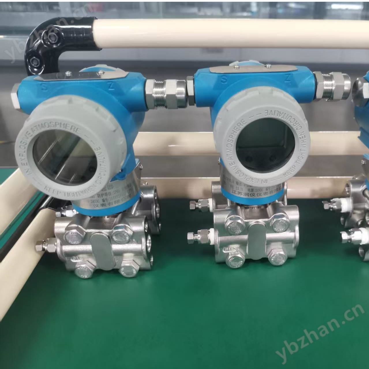
Product Name:Differential pressure transmitter for measuring flue gas
Product Model: JSRY-PB/DP3SJ4
Manufacturer:Jiangsu Runyi Instrument Co., Ltd
Product definition:
Differential pressure transmitter for measuring flue gasIt is suitable for measuring the liquid level, density, and pressure of liquids, gases, or vapors, and then converting them into4~20mA DCSignal output. Intelligent and compatibleHARTThe handheld devices communicate with each other to set, monitor, or form an on-site monitoring system with the upper computer. SK1151/3351DPOn site adjustable intelligent differential pressure transmitter is a transmitter product that can be operated without a manual controller and can achieve on-site zero adjustment, configuration, and other operations through button pressing.
Product Technical Parameters:
Target audience: Differential pressure level transmitter for liquids and liquid mixed vapors.
Measurement range: 0-25Pa to 40MPa
Output signal: 4-20mA DC, intelligent type supports Hart protocol communication (special orders can be ordered with four wire 220V AC power supply 0-10mA DC output)
Power supply: Ordinary transmitter 12-45V DC, explosion-proof transmitter 24V DC
Load characteristics: related to the power supply, with load capacity at a certain power supply voltage. The relationship between load impedance RL and power supply voltage Vs is: RL ≤ 50 (Vs-12)
Indicator: An ammeter can be used for on-site output indication, and our company can provide linear indication 0-100% and square root indication 0-100% meter heads; 3 1/2 digit LCD digital display table, with 13mm high output displayed as a percentage.
Explosion proof: Our factory produces two types of explosion-proof transmitters: a. Explosion proof dIIBT4; b、 Intrinsically safe iaIICT6
Range and zero position: externally continuously adjustable, intelligent models require Hart operator/software or in shell adjustment
Positive and negative migration: The maximum positive migration of the differential pressure transmitter is 500%, and the maximum negative migration is 600%;
The range ratio of the intelligent transmitter is 100:1
Working temperature: Electronic components: -29~+93 ℃ (ordinary type transmitter)
-20~+60 ℃ (explosion-proof transmitter)
Measuring components: -40~+104 ℃ (filled with silicone oil)
LCD display: -20 to+70 ℃
Environmental humidity: 0-100% RH.
Storage temperature: -40 to+100 ℃
Overload pressure: not exceeding 1.15 times the maximum static pressure (see selection table for maximum static pressure)
Volume change: < 0.16cm3
Damping time: continuously adjustable within 0.2-1.67 seconds (0.1-16 seconds for intelligent models), slightly longer for micro, low differential pressure, and flange transmitters; Damping time is the step response.
Start time: 2 seconds, no preheating required.
Product selection method:
JSRY-PB/DP |
Differential pressure transmitter |
|||||||
code |
measurement range |
|||||||
3 |
0-0.6~6Kpa |
|||||||
4 |
0-4~40Kpa |
|||||||
5 |
0-40~250Kpa |
|||||||
6 |
0-0.16~1.0Mpa |
|||||||
7 |
0-0.4~2.0Mpa |
|||||||
8 |
0-1.6~10.0Mpa |
|||||||
code |
output |
|||||||
E |
4-20mA |
|||||||
S |
intelligent type |
|||||||
code name |
structural material |
|||||||
Flanges and fittings |
exhaust/drain valve |
Isolation membrane |
Fill with liquid |
|||||
22 |
316 stainless steel |
316 stainless steel |
316 stainless steel |
silicone oil |
||||
23 |
316 stainless steel |
316 stainless steel |
HastelloyC |
|||||
24 |
316 stainless steel |
316 stainless steel |
Monel |
|||||
25 |
316 stainless steel |
316 stainless steel |
Tantalum |
|||||
33 |
HastelloyC |
HastelloyC |
HastelloyC |
|||||
35 |
HastelloyC |
HastelloyC |
Tantalum |
|||||
44 |
Monel |
Monel |
Monel |
|||||
code name |
Maximum work pressureMPa |
|||||||
B- |
4 |
|||||||
C- |
10 |
|||||||
D- |
14 |
|||||||
code |
option |
|||||||
M1 |
0-100% linear indicator table |
|||||||
M2 |
LED display table |
|||||||
M3 |
LCD display table |
|||||||
B1 |
Pipe bending bracket |
|||||||
B2 |
Board mounted bending bracket |
|||||||
B3 |
Pipe mounted flat bracket |
|||||||
D1 |
The side relief valve is located at the upper part of the pressure chamber |
|||||||
D2 |
The side relief valve is located at the lower part of the pressure chamber |
|||||||
No note |
1/2NPT taper pipe threaded joint |
|||||||
C0 |
1/2-14NPT spinal threaded joint |
|||||||
C1 |
?1/2-14NPTWelding pressure pipe at the rear of the pressure jointF14 |
|||||||
C2 |
T-shaped threaded jointM20×1.5, with rear weldingF14Spherical cone connector of pressure pipe |
|||||||
d |
Explosion proof typedIIBT4 |
|||||||
i |
Intrinsic safety typeiaⅡCT6 |
|||||||
J |
Flow Transmitter4-20mAFounder's output |
|||||||
s |
Stainless steel three valve group |
|||||||
Similar Product Recommend