-
E-mail
desen118@163.com
-
Phone
15312342373
-
Address
Jinhu County Economic Development Zone, Jiangsu Province
Product Categories
Jiangsu Desen Instrument Co., Ltd
Explosion proof split type electromagnetic flowmeter
NegotiableUpdate on 11/20
- Model
- Nature of the Manufacturer
- Producers
- Product Category
- Place of Origin
Overview
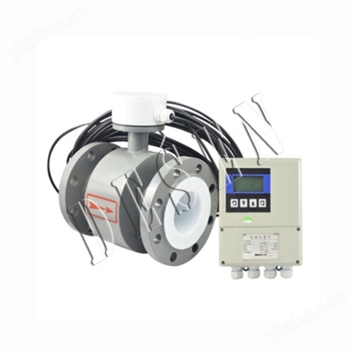
Explosion proof split type electromagnetic flowmeter consists of a sensor and a converter. The sensor is installed on the measuring pipeline, and the converter is installed within 30 meters or 100 meters from the sensor. The two are connected by shielded cables.
Product Details
1、 Instrument Overview:
The split type electromagnetic flowmeter consists of a sensor and a converter. The sensor is installed on the measuring pipeline, and the converter is installed within 30 meters or 100 meters of the sensor. The two are connected by shielded cables. The main components of a flowmeter sensor are: measuring tube, electrode, excitation coil, iron core, and magnetic yoke housing. Mainly used to measure the volumetric flow rate of conductive liquids and slurries in closed pipelines. Such as water, sewage, mud, pulp, various acids, alkalis, salt solutions, food slurries, etc., are widely used in industries such as petroleum, chemical, metallurgical, textile, food, pharmaceutical, papermaking, as well as environmental protection, municipal management, water conservancy construction, etc. to measure high temperature, high humidity, and difficult to observe environments.
IIExplosion proof split type electromagnetic flowmeterWorking Principle:
The split type electromagnetic flowmeter is based on Faraday's principle of electromagnetic induction. A pair of detection electrodes are installed on the pipe wall perpendicular to the axis of the measuring tube and the magnetic field lines. When the conductive liquid moves along the axis of the measuring tube, it cuts the magnetic field lines and generates an induced potential. This induced potential is detected by the two detection electrodes, and the value is proportional to the flow rate. Its value is E=KBVD equation:
E - Induced potential;
K - coefficient related to magnetic field distribution and axial length;
B - Magnetic induction intensity;
V - average flow velocity of conductive liquid;
D - electrode spacing; (Measuring the inner diameter of the tube)
The sensor uses the induced potential E as a flow signal, which is transmitted to the converter. After amplification, transformation, filtering, and a series of digital processing, the instantaneous and cumulative flow rates are displayed on a backlit dot matrix LCD. The converter has 4-20mA output, alarm output and frequency output, and is equipped with communication interfaces such as RS-485, and supports HART and MODBUS protocols.

3、 Advantages:
1. The measurement of flow rate is not affected by changes in fluid density, viscosity, temperature, pressure, and conductivity. The sensor induced voltage signal is linearly related to the average flow rate, resulting in high measurement accuracy.
2. There is no obstruction in the measuring pipeline, so there is no additional pressure loss; There are no movable parts inside the measuring pipeline, so the sensor has an extremely long lifespan.
3. Due to the fact that the induced voltage signal is formed in the entire space filled with a magnetic field and is the average value on the surface of the pipeline, the sensor requires a shorter straight pipe section, with a length of 5 times the diameter of the pipeline.
4. The sensor part only has the inner lining and electrodes in contact with the measured liquid. As long as the electrode and inner lining materials are selected reasonably, they can be corrosion-resistant and wear-resistant.
5. The LD converter adopts microcontroller (MCU) and surface mount technology (SMT), which have reliable performance, high accuracy, low power consumption, stable zero point, and convenient parameter setting. Click on the Chinese display LCD to show accumulated flow, instantaneous flow, flow rate, flow percentage, etc.
6. Measurement system, capable of measuring forward flow and reverse flow. Using special production processes and high-quality materials to ensure stable product performance over a long period of time.
7. Suitable for measuring the volumetric flow rate of conductive liquids and slurries in closed pipelines, such as clean water, sewage, various acid-base salt solutions, mud, slurry, pulp, and liquids related to food.
4、 Flow meter structure form:
1. Sensor:
The sensor mainly consists of a measuring conduit, measuring electrodes, excitation coils, iron cores, magnetic yokes, and a housing.
a、 Measurement catheter: composed of stainless steel catheter, lining, and connecting flange, it is a carrier for measuring the on-site working conditions of the measured liquid.
b、 Measurement electrode: a pair of electrodes installed on the inner wall of the measurement catheter, perpendicular to the axial flow direction, to generate signals for the measured liquid.
c、 Excitation coil: The upper and lower excitation coils that generate a magnetic field inside the measuring conduit.
d、 Iron core and magnetic yoke: Introduce the magnetic field generated by the excitation coil into the liquid and form a magnetic circuit.
e、 Shell: Instrument outer packaging.
2. Converter: It is an intelligent secondary meter that amplifies and processes flow signals. After being operated by a microcontroller, it can display flow and cumulative measurement, and output signals such as pulses and analog currents for measuring or controlling fluid flow.
3. Product assembly form: It is divided into two forms: integrated and split.
a、 Integrated: The sensor and converter are installed together.
b、 Split type: Sensors and converters are installed separately, forming a flow metering system through connecting cables.
c、 To meet the requirements of measuring different media, there are multiple choices for the lining and electrode materials of sensors.
5Explosion proof split type electromagnetic flowmeterPerformance indicators:
1. Instrument accuracy: pipeline type 0.5 level, 1.0 level; Insertion type 2.5 level.
2. Measurement medium: various liquid and liquid-solid two-phase fluids with conductivity greater than 5 μ S/cm.
3. Flow velocity range: 0.2-8m/s.
4. Work pressure: 1.6MPa.
5. Environmental temperature: -40 ℃ to+50 ℃.
6. Medium temperature: PTFE lining ≤ 180 ℃; Rubber material lining ≤ 65 ℃.
7. Explosion proof mark: Exmibd Ⅱ BT4.
8. Explosion proof certificate number: GYB01349.
9. External magnetic interference: ≤ 400A/m.
10. Shell protection: Integrated type: IP65. Detached type: Sensor IP68 (5 meters underwater, with rubber lining) Converter IP65.
11. Output signal: 4-20mA.DC, load resistance 0-750 Ω.
12. Communication output: RS485 or CAN bus.
13. Electrical connection: M20 × 1.5 internal thread, φ 10 cable hole.
14. Power supply voltage: 90-220V.AC, 24 ± 10% V.DC.
15. Maximum power consumption: ≤ 10VA.
6、 Main advantages and disadvantages:
1. The sensor structure is simple, with no movable parts inside the measuring tube and no throttling components that hinder fluid flow. So when the fluid passes through the flowmeter, it will not cause any additional pressure loss, making it one of the flow meters with the lowest operating energy consumption.
2. It can measure the flow rate of contaminated media, corrosive media, and suspended liquid-solid two-phase flow. This is because the internal flow components of the instrument measuring tube only come into contact with the inner lining and electrodes of the measuring tube, and their materials can be selected according to the properties of the measured fluid. For example, using polytetrafluoroethylene or polytetrafluoroethylene as lining can measure various corrosive media such as acids, alkalis, salts, etc; The use of wear-resistant rubber as an inner lining is particularly suitable for measuring liquid-solid two-phase flows such as slurry and cement slurry with solid particles and high wear, as well as various suspended liquids such as fibrous liquids and pulp.
3. It is a volumetric flow measurement instrument that is not affected by the temperature, viscosity, density, or conductivity (within a certain range) of the measured medium during the measurement process. Therefore, after being calibrated with water, electromagnetic flow meters can be used to measure the flow rate of other conductive liquids.
4. The output is only proportional to the average flow velocity of the measured medium, and is independent of the flow state under symmetric distribution (laminar or turbulent). So the range of electromagnetic flow meters is extremely wide, with a measurement range of up to 100:1, and some even have an operational flow range of up to 1000:1.
5. No mechanical inertia, sensitive response, can measure instantaneous pulsating flow, and can also measure flow in both positive and negative directions.
6. The range of calibers is extremely wide, from a few millimeters to several meters, and there are already real flow calibration equipment with calibers up to 3m in China, laying the foundation for the application and development of electromagnetic flowmeters.
The main shortcomings that still exist at present are as follows:
1. Cannot be used to measure gases, vapors, and liquids containing large amounts of gas.
2. It cannot be used to measure liquid media with very low conductivity, such as petroleum products or organic solvents. Currently, electromagnetic flow meters are powerless.
3. Ordinary industrial electromagnetic flow meters cannot be used to measure high-temperature media due to the limitations of measuring pipe lining materials and electrical insulation materials; Without special treatment, it cannot be used for measuring low-temperature media to prevent insulation damage caused by condensation (frost) outside the measuring tube.
4. Electromagnetic flow meters are susceptible to external electromagnetic interference.
7、 Selection of installation environment:
In order to ensure stable operation of the transmitter, the following requirements should be noted when selecting the installation environment:
1. Try to avoid ferromagnetic objects and specific equipment with strong electromagnetic fields (such as large motors, transformers, etc.) to prevent the magnetic field from affecting the working magnetic field and flow information of the sensor.
2. It should be installed in a dry and ventilated place as much as possible, and should not be installed in damp or water prone areas.
3. Avoid direct sunlight and rain as much as possible, and avoid environments with temperatures above 45 ℃ and relative humidity above 95.9%.
4. Choose a place that is easy to maintain and has convenient activities.
5. The flowmeter should be installed at the rear end of the water pump and must not be installed on the suction side; The valve should be installed on the downstream side of the flowmeter.
8、 Installation requirements for straight pipe sections:
Sensors have certain requirements for the upstream and downstream straight pipe sections of the installation point, otherwise it will affect the measurement accuracy.
1. If there is a tapered pipe upstream of the sensor installation point, there should be an equal diameter straight pipe section of not less than 15D upstream of the sensor and an equal diameter straight pipe section of not less than 5D downstream.
2. If there is a gradually expanding pipe upstream of the sensor installation point, there should be an equal diameter straight pipe section of not less than 18D upstream of the sensor, and an equal diameter straight pipe section of not less than 5D downstream.
3. If there is a 90 ° elbow or lower joint upstream of the sensor installation point, there should be an equal diameter straight pipe section of not less than 20D upstream of the sensor, and an equal diameter straight pipe section of not less than 5D downstream.
4. If there are two 90 ° elbows on the same plane upstream of the sensor installation point, there should be an equal diameter straight pipe section of not less than 25D upstream of the sensor and an equal diameter straight pipe section of not less than 5D downstream.
5. If there are two 90 ° elbows on different planes upstream of the sensor installation point, there should be an equal diameter straight pipe section of not less than 40D upstream of the sensor and an equal diameter straight pipe section of not less than 5D downstream.
6. The flow regulating valve or pressure regulating valve should be installed as much as possible outside 5D downstream of the sensor. If it must be installed upstream of the sensor, there should be an equal diameter straight pipe section of not less than 50D upstream and an equal diameter straight pipe section of not less than 5D downstream.
Special attention
1. If a valve is installed near the upstream of the sensor installation point, constantly opening and closing the valve will have a great impact on the service life of the sensor, and it is very easy to cause * damage to the sensor.
2. Sensors should be avoided as much as possible from being installed on very long overhead pipelines. Over time, the sagging of the sensor can easily cause sealing leakage between the sensor and the flange. If installation is necessary, pipeline fastening devices must be installed at 2D positions upstream and downstream of the sensor.
9、 Installation precautions:
1. The sensor should be installed vertically and the fluid should flow from bottom to top to ensure that the solid and liquid phases are in a mixed state. The reason is that solid objects (such as sediment, small stone particles, etc.) in the medium are prone to precipitation. In addition, if there are fish and weeds in the pipeline, the movement of fish in the pipeline will cause the output of the flowmeter to oscillate back and forth; The back and forth swing of weeds hanging near the electrode can also cause instability in the output of the flowmeter. Install a metal filter at the upstream inlet of the flowmeter to block fish and weeds from entering the measuring tube.
2. Improper setting and operation of the pipeline to prevent negative pressure may cause negative pressure to be generated inside the sensor. When the valves upstream and downstream of the flowmeter are closed simultaneously, if the temperature of the fluid is higher than the air temperature, it will shrink after cooling, which poses a risk of forming negative pressure inside the pipe. Negative pressure causes the lining to peel off from the metal conduit, resulting in electrode leakage.
3. Add a negative pressure prevention valve near the flowmeter, open the valve to connect to atmospheric pressure to prevent negative pressure from being generated inside the sensor. When a vertical pipeline is connected downstream of the flowmeter, if the upstream valve of the flow sensor is used to close or adjust the flow rate, negative pressure will be formed inside the measuring tube of the sensor. To prevent negative pressure, it is necessary to add back pressure or use downstream valves to regulate and close the flow rate.
4. Adequate maintenance space is often required for large-diameter flow meters to be installed in instrument wells for the convenience of pipeline installation, wiring, inspection, and maintenance. For the convenience of observation, wiring, and maintenance, instrument installation should be at a certain height from the ground for easy cleaning and installation.
10、 Troubleshooting:
During operation, various faults may cause inaccurate measurements. Generally, the faults caused by electromagnetic flow meters during operation can be divided into two categories. One type is caused by the malfunction of the flowmeter itself or damage to its components; One type of fault is caused by changes in external conditions, such as unstable output, countless flows, excessive errors, etc. Here are several simple troubleshooting methods:
a、 Unstable output: 1. Unstable flow field; 2. The liquid detected by the sensor contains gas and large solid blocks; 3. Electrical connection virtual connection; 4. Poor grounding; 5. Solution to electrode leakage: 1. Modify the pipeline or install fake sensors; 2. Normal phenomena; 3. Check the wiring and connect the wires properly; 4. Connect the ground wire properly; 5. Repair the sensor.
b、 Liquid flow without output: 1. Reverse the two core wires of the signal transmission cable between the converter and the liquid flow; 2. The power supply is not connected or has poor contact; 3. There is leakage in the sensor instrument pipeline, housing, and end face. Solution: 1. Reverse the wire head; 2. Connect the power supply and maintain good contact; 3. Repair the sensor.
c、 Liquid does not flow but has output: 1. There is a broken circuit in the signal transmission cable connection between the converter and the liquid; 2. The signal cable is disconnected from the electrode connection; 3. Surface contamination or deposition of insulation layer on the electrode; 4. Poor grounding or open circuit. Solution: 1. Connect the cable properly; 2. Open the sensor and reconnect it; 3. Clean the surface of the electrode; 4. Connect the ground wire properly.
d、 Excessive error: 1. Zero point too high; 2. Not filled with liquid; 3. Excessive distortion of the power supply; 4. Poor grounding. Solution: 1. Adjust the zero point again; 2. Improve pipeline conditions, with sensors always filled with liquid; 3. Improve the power supply conditions to meet normal working conditions; 4. Connect the ground wire properly.
11、 Main technical data:
1. Technical data of the whole machine and sensors
execution standard |
JB/T 9248—1999 |
||||
Nominal Diameter |
10. 15, 20, 25, 32, 40, 50, 65, 80, 100, 125, 150, 200, 250, 300, 350, 400, 500, 600, 700, 800, 900, 1000, 1200, 1400, 1600, 1800, 2000, 2200, 2400, 2600, 2800, 3000 |
||||
Zui high flow rate |
15m/s |
||||
accuracy |
DNl5~DN600 |
Indication: ± 0.3% (flow rate ≥ 1m/s); ± 3mm/s (flow rate<1m/s) |
|||
DN700—DN3000 |
± 0.5% of the indicated value (flow rate ≥ 0.8m/S); ± 4mm/s (flow rate<0.8m/S) |
||||
Fluid conductivity |
≥5uS/cm |
||||
Nominal Pressure |
4.0MPa |
1.6MPa |
1.0MPa |
0.6MPa |
6.3、10MPa |
DNl0~DN80 |
DN100~DN150 |
DN200~DN1000 |
DN1200~DN2000 |
Special Orders |
|
ambient temperature |
sensor |
-25 ℃ -+60 ℃ |
|||
Converter and integrated model |
-10 ℃ -+60 ℃ |
||||
Lining material |
Polytetrafluoroethylene, chloroprene rubber, polyurethane, perfluoroalkoxy (F46), mesh PFA |
||||
Zui high fluid temperature |
- Body type |
70℃ |
|||
Separated type |
Polychloroprene rubber lining |
80℃; 120 ℃ (specify when ordering) |
|||
Polyurethane lining |
80℃ |
||||
PTFE lining |
100℃; 150 ℃ (specify when ordering) |
||||
Perfluoroethylene propylene (F46) | |||||
Mesh PFA | |||||
Signal electrode and ground electrode materials |
Stainless steel 0Crl8Nil2M02Ti, Hastelloy C, Hastelloy B, titanium, tantalum, platinum/iridium alloy, stainless steel coated with tungsten carbide |
||||
Electrode mechanism |
DN300—DN3000 |
||||
Connecting flange material |
carbon steel |
||||
Grounding flange material |
Stainless steel 1Cr18Ni9Ti |
||||
Imported protective flange materials |
DN65—DNl50 |
Stainless steel 1Cr18Ni9Ti |
|||
DN200~DNl600 |
Carbon steel and stainless steel 1Cr18Ni9Ti |
||||
Shell protection |
DNl5~DN3000 separable rubber or polyurethane lined sensor |
IP65 or IP68 |
|||
Other sensors, body type flow meters, and separate converters |
IP65 |
||||
Distance (separated type) |
The distance between the converter and the sensor is generally not more than 100m |
||||
2. Converter technology data
power supply |
communication |
85—265V,45—400Hz |
direct current |
11—40V |
|
Operation keys and display |
push-button |
Four thin film buttons can be used to set and select all parameters, and the converter can also be programmed using a PC (RS232); 3-line LCD with wide viewing angle, wide temperature, and backlit display; The first line displays the traffic value; The second line displays the flow unit; The third line displays the percentage of traffic, total forward, total reverse, total difference, alarm, and flow rate. |
Magnetic key type |
Two magnetic keys are used for selecting and resetting display parameters, and the converter is programmed using a PC (RS232); 2-line LCD display with wide viewing angle, wide temperature, and backlight: Line 1: Magnetic key selection: Display flow percentage, forward total amount, reverse total amount, difference total amount, alarm, and flow rate. Line 2: Display traffic. |
|
Internal integrator |
Positive total, negative total, and differential total. |
|
output signal |
Unidirectional analog output |
Fully isolated, load ≤ 600D. (at 20mA); Upper limit: 0-21mA optional, 1mA per level; Lower limit: 0-21mA optional, 1mA per level; programming for forward and reverse flow output modes. |
Bidirectional analog output |
The lower limit is. Or 4mA, other same unidirectional analog outputs. |
|
Bidirectional pulse output |
Two outputs correspond to forward and reverse flow rates, with a frequency range of 0-800Hz and an upper limit of 1-800Hz to choose from. Each IHz level is available; Square wave or selected pulse width, with an upper limit of 2.5S and 1ms per step; passive isolation transistor switch output, capable of absorbing 250mA current and withstanding 35V voltage. |
|
Dual channel alarm output |
Programmable alarm for high/low flow rate, air traffic control, fault status, positive/negative flow rate, analog over range, pulse over range, pulse small signal cutoff, with optional output polarity; Transistor switch output with isolation protection, capable of absorbing 250mA current and withstanding 35V voltage (not isolated from pulse output) |
|
Digital Communication |
RS232,RS485,HART |
|
3. Selection of lining
Lining material |
Main performance |
Zui high medium temperature |
Scope of Application |
|
- Body type |
Separated type |
|||
Polytetrafluoroethylene (F4) |
It is a plastic with the most stable chemical properties, capable of withstanding boiling hydrochloric acid, sulfuric acid, nitric acid, and aqua regia, as well as concentrated alkali and various organic solvents. Not resistant to corrosion from high flow rate liquid fluorine, liquid oxygen, and self oxygen. |
70℃ |
100 ℃ 150 ℃ (special order required) |
1. Strong corrosive media such as concentrated acid and alkali. 2. Sanitary media. |
Perfluoroethylene propylene (F46) |
Same as F4, its wear resistance and negative pressure resistance are higher than F4. |
Ditto. |
||
Polyfluoroethylene (Fs) |
The upper limit of applicable temperature is lower than that of polytetrafluoroethylene, but the cost is also lower. |
80℃ |
||
polychloroprene rubber |
1. Some have elasticity, high tensile strength, and good wear resistance. 2. Resistant to corrosion in general low concentration acid, alkali, and salt media, but not resistant to corrosion in oxidizing media. |
80 ℃ 120 ℃ (special order required) |
Water, sewage, and weakly abrasive slurry. |
|
polyurethane rubber |
1. Wear resistance *. |
80℃ |
Neutral strong abrasion slurry, coal slurry, mud |
|
4. Selection of imported protective flanges and grounding flanges (or grounding rings)
Type of flange |
Scope of application |
Grounding flange (or grounding ring) |
Suitable for non-conductive pipelines such as plastic pipes, but sensors with grounding electrodes do not require them. |
Import protection flange |
Choose when the medium has strong wear resistance. |
5. Selection of electrodes
electrode material |
Corrosion resistance and wear resistance |
Stainless steel 0Crl8Nil2M02Ti |
Used for weakly corrosive media such as industrial water, domestic water, sewage, etc., suitable for industrial sectors such as petroleum, chemical, steel, as well as municipal and environmental protection fields. |
哈氏合金B |
It has good corrosion resistance to all concentrations of hydrochloric acid below boiling point, as well as to non chlorinated acids, bases, and non oxidizing salt solutions such as sulfuric acid, phosphoric acid, and organic acids. |
Hastelloy C |
Can withstand corrosion from non oxidizing acids such as nitric acid, mixed acids, or mixed media of chromic acid and sulfuric acid, as well as corrosion from oxidizing salts such as Fe, Cu, or other oxidants such as hypochlorite solutions above room temperature and seawater |
Titanium |
Capable of withstanding corrosion from seawater, various chlorides and hypochlorites, oxidizing acids (including fuming sulfuric acid), organic acids, and alkalis. Not resistant to the corrosion of relatively pure reducing acids (such as sulfuric acid, hydrochloric acid), but if the acid contains oxidants (such as nitric acid, Fc++, Cu++), the corrosion is greatly reduced. |
Tantalum |
It has excellent corrosion resistance and is very similar to glass. Except for fuming sulfuric acid and alkali, it can almost withstand corrosion from cutting chemical media (including boiling point hydrochloric acid, nitric acid, and sulfuric acid below 50 ℃). Dig in alkali; Corrosion resistance. |
Platinum/titanium alloy |
Almost capable of cutting chemical media, but not suitable for aqua regia and ammonium salts. |
Stainless steel coated with tungsten carbide |
Used for non corrosive and highly abrasive media. |
Note: Due to the wide variety of media and the complex factors such as temperature, concentration, and flow rate that affect their corrosiveness, this table is for reference only. Users should make their own choices based on the actual situation, and if necessary, conduct corrosion resistance tests on the selected materials, such as hanging plate tests. | |
12、 Correct selection:
The selection of instruments is a very important task in instrument applications. Relevant data shows that 2/3 of instrument failures in practical applications are caused by incorrect selection or installation of instruments. Please pay special attention.
1. Collect data:
The composition of the fluid being tested;
Zui high traffic, Zui low traffic;
The highest work pressure;
Zui high temperature, Zui low temperature;
2. Range confirmation:
The flow rate of the measured medium in general industrial flow meters should be between 2-4m/s. In special cases, the minimum flow rate should not be less than 0.2m/s, and the maximum flow rate should not be greater than 8m/s. If the medium contains solid particles, the commonly used flow rate should be less than 3m/s to prevent excessive friction between the lining and the electrode; For viscous fluids, the flow velocity can be chosen to be greater than 2m/s. A higher flow velocity helps to automatically eliminate the effect of viscous substances attached to the electrode, which is beneficial for improving measurement accuracy.
Under the condition that the range Q has been determined, the size of the flowmeter diameter D can be determined based on the range of flow velocity V mentioned above, and its value can be calculated by the following formula:
Q=πD2V/4
Q: Flow rate (㎡/h) D: Inner diameter of pipeline V: Flow rate (m/h)
The electromagnetic range Q should be greater than the expected maximum flow rate value, while the normal flow rate value should be slightly greater than 50 times the full scale of the flowmeter.
3. Reference flow range:
Caliber (mm) |
Flow range (m3/h) |
Caliber (mm) |
Flow range (m3/h) |
φ15 |
0.06~6.36 |
φ450 |
57.23~5722.65 |
φ20 |
0.11~11.3 |
φ500 |
70.65~7065.00 |
φ25 |
0.18~17.66 |
φ600 |
101.74~10173.6 |
φ40 |
0.45~45.22 |
φ700 |
138.47~13847.4 |
φ50 |
0.71~70.65 |
φ800 |
180.86~18086.4 |
φ65 |
1.19~119.4 |
φ900 |
228.91~22890.6 |
φ80 |
1.81~180.86 |
φ1000 |
406.94~40694.4 |
φ100 |
2.83~282.60 |
φ1200 |
553.90~55389.6 |
φ150 |
6.36~635.85 |
φ1600 |
723.46~72345.6 |
φ200 |
11.3~1130.4 |
φ1800 |
915.62~91562.4 |
φ250 |
17.66~176.25. |
φ2000 |
1130.4~113040.00 |
φ300 |
25.43~2543.40 |
φ2200 |
1367.78~136778.4 |
φ350 |
34.62~3461.85 |
φ2400 |
1627.78~162777.6 |
φ400 |
45.22~4521.6 |
φ2600 |
1910.38~191037.6 |
4. Selection Table:
Specification Model |
管道口径 |
Material: Carbon Steel and Stainless Steel |
||||
DS-LDE |
15~2600 |
|||||
code name |
electrode material |
|||||
K1 |
316L |
|||||
K2 |
HB |
|||||
K3 |
HC |
|||||
K4 |
Titanium |
|||||
K5 |
Tantalum |
|||||
K6 |
Platinum alloy |
|||||
K7 |
Stainless steel coating Tungsten carbide coating |
|||||
code name |
Lining material |
|||||
C1 |
Polytetrafluoroethylene F4 |
|||||
C2 |
Perfluoroethylene propylene F46 |
|||||
C3 |
Polyfluoroethylene FS |
|||||
C4 |
Polyvinyl rubber |
|||||
C5 |
Polyurethane rubber |
|||||
code name |
function |
|||||
E1 |
Level 0.3 |
|||||
E2 |
Level 0.5 |
|||||
E3 |
Level 1 |
|||||
F1 |
4-20Madc, Load ≤ 750 Ω |
|||||
F2 |
0-3kHz, 5V active, variable pulse width, output effective frequency |
|||||
F3 |
RS485 interface |
|||||
T1 |
Room temperature type |
|||||
T2 |
high-temperature type |
|||||
T3 |
Ultra high temperature type |
|||||
P1 |
1.0MPa |
|||||
P2 |
1.6MPa |
|||||
P3 |
4.0MPa |
|||||
P4 |
16MPa |
|||||
D1 |
220VAC±10% |
|||||
D2 |
24VDC±10% |
|||||
J1 |
Integrated structure |
|||||
J2 |
Split type structure |
|||||
J3 |
Explosion proof integrated structure |
|||||
DS-LDE |
100 |
K1 |
C1 |
E2 |
F1T1P3D1J2 |
Desen electromagnetic flowmeter |
13、 Ordering Notice:
1. Product: If there are model standards, please call directly to inquire about prices and learn more details!
2. If there are no product model specifications, please send the operating requirements, design drawings, and technical specifications to our company.
3. Product ordering requires parameters such as diameter (DN), nominal pressure (Mpa), temperature (℃), flow range (m3/h), medium name (such as water), connection method (clamp type, threaded type, flange type, clamping type, split type, insertion type, etc.).
4. Quotation confirmation: Our company provides a quotation list and technical standard specifications to the customer for confirmation. After both parties confirm the technical aspects, the contract will be drafted.
5. Quality requirements, quality standards, and conditions for suppliers to be responsible for quality: in accordance with relevant national quality standards.
After-sales service
1. From the date of contract signing, our company provides free maintenance and upkeep services for the products provided, and promises lifelong repair services;
2. Jiangsu Desen Instrument Co., Ltd. will regularly communicate with customers to understand the usage of the product and solve any problems that arise during their use, providing free services;
3. During the warranty period, if there is any man-made damage, our company is responsible for repairing it and collecting the repair costs incurred;
4. If there are quality problems or dissatisfaction with the product, users can choose to return or exchange it unconditionally. The company does not charge any handling fees. If there are quality problems, the company will bear the round-trip shipping costs.
Similar Product Recommend


