-
E-mail
wfhuaguang@126.com
-
Phone
13806491159
-
Address
Jinyu Huangting Business Building, Kuiwen District, Weifang City, Shandong Province (Headquarters of Huaguang High tech Group)
Product Categories
Weifang Huaguang High tech Electronics Co., Ltd
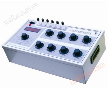
HGZX5KV megohmmeter calibrator
NegotiableUpdate on 09/27
- Model
- Nature of the Manufacturer
- Producers
- Product Category
- Place of Origin
Overview
1、 Introduction: HGZX5KV Megohmmeter Calibration Device | Megohmmeter Calibration Device | Insulation Resistance Meter Calibration Device HGZX5KA Megohmmeter Calibration Device is based on the requirements of JJG1005-2005 "Electronic Insulation Resistance Meter Calibration Regulations" and JJG622-1997 "Insulation Resistance Meter (Megohmmeter) Calibration Regulations" for relevant calibration items
Product Details
1、 Introduction
HGZX5KV Megohmmeter Calibration Device | Megohmmeter Calibration Device | Megohmmeter Calibration Device | Insulation Resistance Meter Calibration Device
HGZX5KA megohmmeter calibratorIt is a specialized equipment designed and manufactured in accordance with the requirements of JJG1005-2005 "Verification Regulations for Electronic Insulation Resistance Meters" and JJG622-1997 "Verification Regulations for Insulation Resistance Meters (Megohmmeters)", and with reference to the relevant content of the general technical conditions of the power industry standard DL/T845.1-2004 "Electronic Insulation Resistance Meters". It is used to verify the indication error, drop voltage, and short-circuit current of electronic insulation resistance meters. In conjunction with the constant speed device (CY3 type) produced by our company, it can verify the indication error, open circuit voltage, median voltage, and peak voltage of the pointer type megohmmeter. It has the characteristics of compact structure, stable performance, and easy use. It is an ideal equipment used by various industrial and mining enterprises and institutions to calibrate various types of insulation resistance meters.
2、 Main technical indicators
The HGZX5KV insulation resistance meter calibration device (megohmmeter calibration device) is mainly used to calibrate various types of insulation resistance meters with rated voltage ≤ 5000V, and can also be used as a standard instrument in the production and repair of insulation resistance meters. The resistor part can be used separately. The digital meter can measure a maximum DC voltage of 5000V and a maximum DC current of 20mA.
The main technical performance of this verification device is as follows:
A standard numerical table
1. Measurement range:
Voltage is divided into two levels: 0-500V and 0-5000V
Short circuit current: 0-2mA 0-20mA
2. Basic error:
|
DC voltage |
≤ 500V: ± (0.4% reading+0.1% full-scale) > 500V: ± (0.5% reading+0.5% full degree) |
|
Peak voltage |
≤ 500V: ± (1% reading+0.5% full degree) > 500V: ± (0.5% reading+0.5% full degree) |
|
short-circuit current |
± (0.3% reading+0.2% full degree) |
3. The response time of the digital meter is about 25 seconds.
㈡Standard resistancedevice
1Standard resistanceThe device consists of a 100G fixed resistor and eight resistor disks
100GΩ+9×10⁴ MΩ+10×(103+102+10+1+0.1+0.01
+0.001)MΩ,
0-20111.1110M Ω, minimum step size 1K Ω, maximum withstand voltage 5KV.
2. The level index and maximum operating voltage or current of each ten inch disk
3. The residual resistance value is less than 1 Ω, and the variation is not greater than 0.1 Ω.
4. Environmental reference conditions: 20+2-3 ℃, relative humidity: 50% ± 10%
5. Nominal operating environment: temperature 23 ± 5 ℃, relative humidity 25% to 60%.
6. Insulation resistance of the circuit to the shell: ≥ 1 × 10¹¹ Ω. 8KV one minute test.
8. Power supply voltage: AC220V 50HZ.
9. Dimensions: 530mm × 250mm × 170mm.
10. Weight: Approximately 17kg.
3、 Panel settings and instructions
This verification device consists of a standard digital meter andStandard resistanceIt consists of two parts.
1. The standard digital meter can be used to measure voltage and current, and is arranged on the left side of the device
For ease of use, its voltage and current input terminals are separately set. The left middle is an LED display with a larger display size to increase the visible distance. The digital meter measurement selection switch is located in the lower left corner, and different test items and ranges can be selected according to measurement needs.
Individual character description on the panel: Uk - open circuit voltage Uf - peak voltage
UZ - median voltage Ud - drop voltage
Id - Short circuit current
2Standard resistanceThe device is designed and manufactured based on the principle of resistance series connection, and the output resistance value is changed by rotating a ten pin disc switch. The resistor consists of two terminals and eight switch structures
The resistance value between two terminals is determined by adding the readings from each reading panel.
4、 Usage method
1. The indication error (basic) of the insulation resistance meter should be wired according to the method in Figure 2, and then the power of the electronic insulation resistance meter should be turned on to start the constant speed drive of the pointer type insulation resistance meter. The indication error and tilt effect of the insulation resistance meter should be verified point by point according to the methods and requirements of the verification regulations.
2. The wiring for verifying the peak open circuit voltage and short-circuit current of the insulation resistance meter is shown in Figure 3. Set the "measurement selection" switch of this device to the corresponding position to start the test.
3. The wiring diagram for verifying the median (drop) voltage of the insulation resistance meter is shown in Figure 4. Refer to Appendix 2 and Appendix 3 to determine the inspected tableMedian resistanceValue, the device'sStandard resistanceAdjust the device to this resistance value and place the "measurement selection" switch in the appropriate position to test.
5、 Precautions for use
1. When using this verification device, the environment should meet the relevant requirements mentioned above. The instrument should have a good grounding wire.
2. When the calibration device has not been used for a long time, it should be checked before useStandard resistanceThe switches of the device should be rotated back and forth several times from 0 to 10 (9) to ensure stable and reliable contact.
3. When using, attention should be paid to the actual applicationStandard resistanceThe voltage on the device should not exceed the maximum operating voltage of each resistor disk to avoid causing the resistor components to exceed the tolerance or even damage.
4. Due to the long time constant (about 25S) of a digital voltmeter, it is necessary to stop the rotation of the constant speed device or turn off the power of the electronic insulation meter after one measurement is completed, and set the "range selection" to the "discharge" position. When the high voltage drops below one hundred volts, the range or measurement items should be changed to ensure the safety of the testing personnel and equipment.
5. During the measurement process, if the voltmeter flashes one light and one dark, it indicates that the input voltage is too high or the range is incorrect, or the switch position is not placed correctly, and it needs to be switched to the correct range.
6. When measuring the peak voltage of this product, zero compensation method is used to overcome peak sampling
The forward voltage drop of the rectifier in the circuit. Therefore, the Uf file does not have an input signal and has a certain size
7. The insulation strength of the circuit to the shell should be able to withstand a 50Hz sine wave voltage
Appendix 1
|
Megameter model |
Median resistancevalue |
|
ZC25—3(旧5050型) |
10MΩ |
|
ZC11D—8 |
2MΩ |
|
ZC11—8 |
2MΩ |
|
ZC25—4(旧1010型) |
20MΩ |
|
ZC11D—3 |
20MΩ |
|
ZC11D—5 |
100MΩ |
|
ZC11D—10 |
50MΩ |
|
ZC11—10 |
50MΩ |
|
ZC11—5 |
100MΩ |
The zero position of the composition is a normal phenomenon.
Special reminder: When calibrating the standard digital meter of this device, it is necessary to note that the signal of the standard source must be returned to zero according to the usual procedure before turning the "range selection" switch to avoid accidental damage to the standard source.
6、 Supplementary Provisions
1. Randomly supplied files and attachments:
(1) Packing list copy
(2) One copy of the user manual
(3) One copy of product qualification certificate
(4) One payment for testing line
(5) One power cord
2. Within 12 months from the date of shipment from the manufacturer, if the product cannot function properly due to poor quality, our factory will repair it for the user free of charge, provided that the user complies with the storage and use rules.
Appendix 2
JJG1005-2005 "Electronic Insulation Resistance Meter"Median resistanceRequirements for selecting drop resistors:
1. Allowable value of median voltage for measuring terminals with a pointer meter
When the pointer type meter indicates the value on the scale line with the closest scale value to the geometric center position, the voltage between terminals L and E should be measured as the median voltage, which should not be lower than 90% of the rated voltage. The center division resistance value of a pointer type meter is generally 2% to 2.5% of the upper range limit
1. Allowable drop pressure value for digital meters
When the display value of the digital meter is the drop resistance value provided by the manufacturer, the voltage between terminals L and E is measured as the drop voltage,
Its value should not be lower than 90% of the rated voltage. The drop resistance value of a digital meter should be within 1% of the upper limit of the basic measurement limit.