-
E-mail
desen118@163.com
-
Phone
15312342373
-
Address
Jinhu County Economic Development Zone, Jiangsu Province
Product Categories
Jiangsu Desen Instrument Co., Ltd
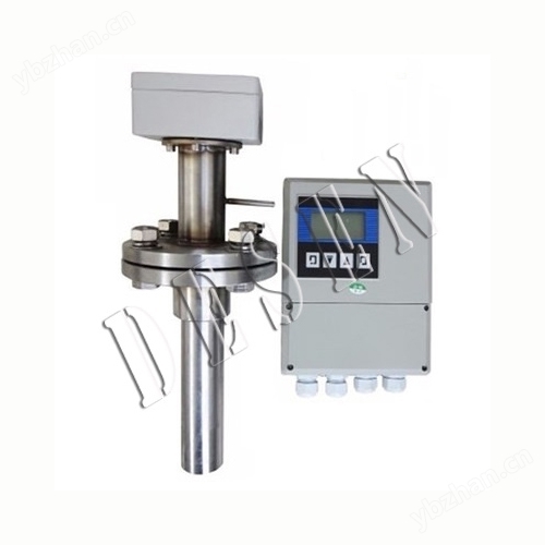
High precision split insertion electromagnetic flowmeter
NegotiableUpdate on 11/20
- Model
- Nature of the Manufacturer
- Producers
- Product Category
- Place of Origin
Overview
High precision split insertion electromagnetic flowmeter is widely used in industries such as petroleum, chemical, metallurgical, textile, food, pharmaceutical, papermaking, as well as environmental protection, municipal management, water conservancy construction, etc.
Product Details
1High precision split insertion electromagnetic flowmeterInstrument Introduction:
The split insertion electromagnetic flowmeter is used to measure conductive liquids, especially suitable for measuring large-diameter pipelines. The flowmeter consists of a sensor and a converter. The sensor is installed on the measuring pipeline, and the converter is installed within 30 meters or 100 meters of the sensor. The two are connected by shielded cables to measure the volumetric flow rate of conductive liquids.
2、 Working principle:
The split insertion electromagnetic flowmeter is based on Faraday's principle of electromagnetic induction. A pair of detection electrodes are installed on the tube wall perpendicular to the axis of the measuring tube and the magnetic field lines. When the conductive liquid moves along the axis of the measuring tube, it cuts the magnetic field lines and generates an induced potential. This induced potential is detected by the two detection electrodes, and the value is proportional to the flow rate. Its value is E=KBVD formula:
E - Induced potential;
K - coefficient related to magnetic field distribution and axial length;
B - Magnetic induction intensity;
V - average flow velocity of conductive liquid;
D - electrode spacing; (Measuring the inner diameter of the tube)
The sensor uses the induced potential E as a flow signal, which is transmitted to the converter. After amplification, transformation, filtering, and a series of digital processing, the instantaneous and cumulative flow rates are displayed on a backlit dot matrix LCD. The converter has 4-20mA output, alarm output and frequency output, and is equipped with communication interfaces such as RS-485, and supports HART and MODBUS protocols.

3、 Application scope:
The split insertion electromagnetic flowmeter is mainly used to measure the volumetric flow rate of conductive liquids and slurries in closed pipelines. Such as water, sewage, mud, pulp, various acids, alkalis, salt solutions, food slurries, etc., are widely used in industries such as petroleum, chemical, metallurgical, textile, food, pharmaceutical, papermaking, as well as environmental protection, municipal management, water conservancy construction and other fields.
4、 Main components:
An electromagnetic flowmeter consists of a sensor and a converter. The sensor is installed on the measuring pipeline, and the converter can be combined with the sensor to form an integrated electromagnetic flowmeter. The converter is installed within 30 meters or 100 meters of the sensor, and is connected by a shielded cable to form a separate electromagnetic flowmeter. The main components of the anti-corrosion electromagnetic flowmeter sensor are: measuring tube, electrode, excitation coil, iron core, and magnetic yoke housing.
5High precision split insertion electromagnetic flowmeterAdvantage:
1. Programmable low-frequency rectangular wave excitation improves the stability of flow measurement and reduces power loss;
2. Adopting a 16 bit embedded microprocessor, it has fast computing speed and high accuracy;
3. All digital processing, strong anti-interference ability, reliable measurement, high accuracy, and a flow measurement range of up to 150:1;
4. Ultra low EMI switching power supply, suitable for a wide range of power supply voltage changes, with good EMC resistance performance;
5. Full Chinese character menu operation, easy to use, simple to operate, easy to learn and understand;
6. High definition backlit LCD display;
7. It has bidirectional flow measurement and bidirectional total accumulation functions, and bidirectional output functions for current and frequency;
8. There are three integrators inside that can display forward cumulative quantity, reverse cumulative quantity, and differential cumulative quantity respectively;
9. Equipped with RS485 or RS232 digital communication signal output
10. Equipped with conductivity measurement function, it can distinguish whether the sensor is empty or not;
11. The constant current excitation current has a wide range and can be used in conjunction with different companies and types of electromagnetic flow sensors;
12. Equipped with self checking and self diagnostic functions;
13. Adopting SMD devices and surface mount (SMT) technology, the circuit has high reliability;
14. The internal design of the instrument includes a non power failure clock that can record 16 power failure times.
6、 Performance indicators:
1. Instrument accuracy: 0.5 level for pipeline type; Insertion type 1.5 level;
2. Measurement medium: various liquid and liquid-solid two-phase fluids with conductivity greater than 5 μ S/cm;
3. Flow velocity range: 0.2-8m/s;
4. Work pressure: 1.6MPa;
5. Environmental temperature: -40 ℃ to+50 ℃;
6. Medium temperature: PTFE lining ≤ 180 ℃.
7. Rubber material lining ≤ 65 ℃;
8. Explosion proof mark: Exmibd Ⅱ BT4;
9. Explosion proof certificate number: GYB01349;
10. External magnetic interference: ≤ 400A/m;
11. Output signal: 4-20mA.DC, load resistance 0-750 Ω;
12. Communication output: RS485 or CAN bus;
13. Electrical connection: M20 × 1.5 internal thread, φ 10 cable hole;
14. Power supply voltage: 90-220V.AC, 24 ± 10% V.DC;
15. Maximum power consumption: ≤ 10VA.
7、 Installation requirements:
1. Selection of installation environment:
a、 Try to stay away from equipment with strong electromagnetic fields, such as large motors, transformers, etc.
b、 The installation site should not have strong vibrations, and the pipeline should be securely fixed. The ambient temperature should not change significantly.
c、 The installation environment should be easy to install and maintain.
2. Selection of installation location:
a、 The position must ensure that the pipeline is always filled with the measured fluid.
b、 Choose a location with small fluid flow pulses. Keep away from local resistance components such as pumps, valves, and elbows.
c、 When measuring two-phase (solid, liquid or gas, liquid) fluids, a location that is not prone to phase separation should be selected.
d、 Negative pressure should be avoided at the measurement site.
e、 The diameter or circumference of the side pipeline should be easy to measure, and the ellipticity should be small.
3. Length of straight pipe section:
The length of the straight pipe section on the upstream side of the sensor installation pipeline should be greater than or equal to 10D, and the downstream side should not be less than 5D. D is the diameter of the measured pipeline.
4. Flow control valves and regulating valves:
The flow control valve should be installed on the measured pipeline upstream of the sensor, and the flow control valve should be installed downstream of the sensor. During measurement, the flow control valve should usually be fully open.
5. The welding requirements for installing the base are as follows:
a、 The axis of the installation base 63 pipe is perpendicular to the axis of the tested pipeline. Its angle is 90 degrees
b、 Use welding rods for flat welding. After welding, ensure that the flange end face is parallel to the pipe axis, the weld seam is firm, and can withstand a pressure of 1.6Mpa without leakage.
c、 The opening size of the tested pipeline and the outer diameter of the through hole of the installation base *.
6. Installation method:
a、 Vertical installation: When inserting the sensor into the pipeline, the angle with the vertical diameter of the pipeline section should be less than 5 °, suitable for measuring clean media with low pipeline vibration.
b、 Tilt installation: The angle between the axis of the sensor and the axis of the measured pipeline is 45 °, which is suitable for measuring the flow rate of liquids with large diameters and other impurities in the measuring medium. This installation method has low water resistance and should not be tangled.
c、 There are two methods for inserting an electromagnetic flow sensor: one is to insert it into the central axis of the measured pipeline, and the other is to insert it into the 0.25D position on the inner wall of the pipeline.
7. Installation of sensors:
a、 Clean the welding slag and burrs on the installation base of the tested tube.
b、 Close the upstream flow control valve or use low-pressure water supply.
c、 Install the DN50 ball valve onto the mounting base. Pay attention to the long cavity of the ball valve facing upwards, check if the ball valve can be fully opened and closed, and install the clamping thread seat, clamping nut, and rubber sealing ring onto the ball valve. Loosen the positioning nut. Insert the sensor into the measured pipeline through a ball valve, while paying attention to the direction of the sensor indicator rod and the direction of the fluid flow.
8、 Troubleshooting:
During operation, flow meters may experience inaccurate measurements due to various malfunctions. Generally, electromagnetic flow meters can cause two types of malfunctions during operation. One type is caused by the malfunction of the flowmeter itself or damage to its components; One type of fault is caused by changes in external conditions, such as unstable output, countless flows, excessive errors, etc. Here are several simple troubleshooting methods:
a、 Unstable output: 1. Unstable flow field; 2. The liquid detected by the sensor contains gas and large solid blocks; 3. Electrical connection virtual connection; 4. Poor grounding; 5. Solution to electrode leakage: 1. Modify the pipeline or install fake sensors; 2. Normal phenomena; 3. Check the wiring and connect the wires properly; 4. Connect the ground wire properly; 5. Repair the sensor.
b、 Liquid flow without output: 1. Reverse the two core wires of the signal transmission cable between the converter and the liquid flow; 2. The power supply is not connected or has poor contact; 3. There is leakage in the sensor instrument pipeline, housing, and end face. Solution: 1. Reverse the wire head; 2. Connect the power supply and maintain good contact; 3. Repair the sensor.
c、 Liquid does not flow but has output: 1. There is a broken circuit in the signal transmission cable connection between the converter and the liquid; 2. The signal cable is disconnected from the electrode connection; 3. Surface contamination or deposition of insulation layer on the electrode; 4. Poor grounding or open circuit. Solution: 1. Connect the cable properly; 2. Open the sensor and reconnect it; 3. Clean the surface of the electrode; 4. Connect the ground wire properly.
d、 Excessive error: 1. Zero point too high; 2. Not filled with liquid; 3. Excessive distortion of the power supply; 4. Poor grounding. Solution: 1. Adjust the zero point again; 2. Improve pipeline conditions, with sensors always filled with liquid; 3. Improve the power supply conditions to meet normal working conditions; 4. Connect the ground wire properly.
9、 Location selection:
In order to ensure stable operation of the transmitter, the following requirements should be noted when selecting the installation location:
1. Try to avoid ferromagnetic objects and specific equipment with strong electromagnetic fields (such as large motors, transformers, etc.) to prevent the magnetic field from affecting the working magnetic field and flow information of the sensor.
2. It should be installed in a dry and ventilated place as much as possible, and should not be installed in damp or water prone areas.
3. Avoid direct sunlight and rain as much as possible, and avoid environments with temperatures above 45 ℃ and relative humidity above 95.9%.
4. Choose a place that is easy to maintain and has convenient activities.
5. The flowmeter should be installed at the rear end of the water pump and must not be installed on the suction side; The valve should be installed on the downstream side of the flowmeter.
10、 Installation precautions:
1. The sensor should be installed vertically and the fluid should flow from bottom to top to ensure that the solid and liquid phases are in a mixed state. The reason is that solid objects (such as sediment, small stone particles, etc.) in the medium are prone to precipitation. In addition, if there are fish and weeds in the pipeline, the movement of fish in the pipeline will cause the output of the flowmeter to oscillate back and forth; The back and forth swing of weeds hanging near the electrode can also cause instability in the output of the flowmeter. Install a metal filter at the upstream inlet of the flowmeter to block fish and weeds from entering the measuring tube.
2. Improper setting and operation of the pipeline to prevent negative pressure may cause negative pressure to be generated inside the sensor. When the valves upstream and downstream of the flowmeter are closed simultaneously, if the temperature of the fluid is higher than the air temperature, it will shrink after cooling, which poses a risk of forming negative pressure inside the pipe. Negative pressure causes the lining to peel off from the metal conduit, resulting in electrode leakage.
3. Add a negative pressure prevention valve near the flowmeter, open the valve to connect to atmospheric pressure to prevent negative pressure from being generated inside the sensor. When a vertical pipeline is connected downstream of a plug-in electromagnetic flowmeter, if the upstream valve of the flow sensor is used to close or adjust the flow rate, negative pressure will be formed inside the sensor measuring tube. To prevent negative pressure, it is necessary to add back pressure or use downstream valves to regulate and close the flow rate.
4. Adequate maintenance space is often required for large-diameter flow meters to be installed in instrument wells for the convenience of pipeline installation, wiring, inspection, and maintenance. For the convenience of observation, wiring, and maintenance, instrument installation should be at a certain height from the ground for easy cleaning and installation.
11、 When grounding protection, the following points must be noted:
1. Sensors and converters should be grounded separately and not connected to motors or process pipelines. The grounding resistance should be less than 10 ohms.
2. The measuring tube, housing, shielding wire, converter, and secondary instrument of the sensor must be grounded.
3. The grounding of sensors and converters should be done on site, and the shielding layer of secondary instruments should be grounded on the control room side. Do not connect multiple terminals to avoid interference caused by different potentials.
4. The sensor is installed on a metal pipeline, and the grounding wire of the sensor can be connected to the pipeline flange according to the manufacturer's requirements to form a reliable grounding circuit. The grounding point of the instrument should be an independent grounding point and cannot be shared with other electrical equipment.
12、 Parameter Comparison Table:
model: |
DS-LDEC series split insertion electromagnetic |
Caliber: |
DN150 - DN2000 |
Accuracy: |
± 2.5% measurement value standard ± 1.5% measurement value special |
Zui low conductivity: |
5μs/cm |
Measurement range: |
Recommended range of use: 0.5m/s~10m/s continuously adjustable |
Medium temperature: |
-20~+150℃ |
Environmental temperature: |
-20~+60℃ |
Fluid pressure: |
≤1.6MPa |
Protection level: |
Sensor converter |
texture of material: |
The probe material is 304 stainless steel, the electrode material is 316 stainless steel, and the insulation layer is PTFE |
Electrical interface: |
M20×1.5,1/2〞NPT |
Display mode: |
Standard dual line LCD display, capable of displaying both instantaneous and cumulative flow rates simultaneously. |
Power Supply: |
220VAC 50HZ; 24VDC |
Explosion proof grade: |
ExdllBT4 |
Signal output: |
1. The switch value can be set as: pulse output (maximum 1000Hz); |
Configuration method: |
1. Configure on-site through three manual keys. |
13、 Correct selection:
The selection of instruments is a very important task in instrument applications. Relevant data shows that 2/3 of instrument failures in practical applications are caused by incorrect selection or installation of instruments. Please pay special attention.
1. Collect data:
The composition of the fluid being tested;
Zui high traffic, Zui low traffic;
The highest work pressure;
Zui high temperature, Zui low temperature;
2. Range confirmation:
The flow rate of the medium measured by the general industrial electromagnetic flowmeter should be 2-4m/s. In special circumstances, the minimum flow rate should not be less than 0.2m/s, and the maximum flow rate should not be greater than 8m/s. If the medium contains solid particles, the commonly used flow rate should be less than 3m/s to prevent excessive friction between the lining and the electrode; For viscous fluids, the flow velocity can be chosen to be greater than 2m/s. A higher flow velocity helps to automatically eliminate the effect of viscous substances attached to the electrode, which is beneficial for improving measurement accuracy.
Under the condition that the range Q has been determined, the size of the flowmeter diameter D can be determined based on the range of flow velocity V mentioned above, and its value can be calculated by the following formula:
Q=πD2V/4
Q: Flow rate (㎡/h) D: Inner diameter of pipeline V: Flow rate (m/h)
The range Q of the electromagnetic flowmeter should be greater than the expected maximum flow value, while the normal flow value should be slightly greater than 50 of the flowmeter's full-scale scale.
14、 Reference flow range:
Caliber mm |
Flow range m3/h |
Caliber mm |
Flow range m3/h |
φ15 |
0.06~6.36 |
φ450 |
57.23~5722.65 |
φ20 |
0.11~11.3 |
φ500 |
70.65~7065.00 |
φ25 |
0.18~17.66 |
φ600 |
101.74~10173.6 |
φ40 |
0.45~45.22 |
φ700 |
138.47~13847.4 |
φ50 |
0.71~70.65 |
φ800 |
180.86~18086.4 |
φ65 |
1.19~119.4 |
φ900 |
228.91~22890.6 |
φ80 |
1.81~180.86 |
φ1000 |
406.94~40694.4 |
φ100 |
2.83~282.60 |
φ1200 |
553.90~55389.6 |
φ150 |
6.36~635.85 |
φ1600 |
723.46~72345.6 |
φ200 |
11.3~1130.4 |
φ1800 |
915.62~91562.4 |
φ250 |
17.66~176.25. |
φ2000 |
1130.4~113040.00 |
φ300 |
25.43~2543.40 |
φ2200 |
1367.78~136778.4 |
φ350 |
34.62~3461.85 |
φ2400 |
1627.78~162777.6 |
φ400 |
45.22~4521.6 |
φ2600 |
1910.38~191037.6 |
15、 Selection Table:
model |
caliber |
Material: Carbon Steel and Stainless Steel |
||||||||
DS-LDEC |
150~2000 |
|||||||||
code name |
install form |
|||||||||
Y |
integrated |
|||||||||
F |
split-type |
|||||||||
code name |
Converter form |
|||||||||
ZA |
Circular converter |
|||||||||
ZB |
Square converter (only applicable to split type) |
|||||||||
code name |
Power supply form |
|||||||||
AC |
(AC) 220V AC 50Hz (90~245V AC 50Hz) |
|||||||||
DC |
(DC) 24V DC (20-36V DC) |
|||||||||
LD |
Lithium battery power supply (without signal output) |
|||||||||
code name |
output signal |
|||||||||
I |
4~20mA |
|||||||||
F |
Frequency 1KHz |
|||||||||
Rs |
Serial communication (485) |
|||||||||
C |
controlled output |
|||||||||
code name |
Explosion-proof requirements |
|||||||||
N |
No explosion-proof |
|||||||||
EX |
Explosion proof (only applicable to split type) |
|||||||||
code name |
Is it equipped with a ball valve |
|||||||||
N |
Without ball valve |
|||||||||
Q |
With ball valve |
|||||||||
code name |
Electrode material |
|||||||||
316L |
stainless steel |
|||||||||
code name |
Wiring is suitable for split type |
|||||||||
10 |
Equipped with 10 meter lead wire (standard) |
|||||||||
15 |
Equipped with a 15 meter lead wire |
|||||||||
… |
and so on |
|||||||||
16、 Ordering Notice:
1. Product: If there are model standards, please call directly to inquire about prices and learn more details!
2. If there are no product model specifications, please send the operating requirements, design drawings, and technical specifications to our company.
3. Product ordering requires parameters such as diameter (DN), nominal pressure (Mpa), temperature (℃), flow range (m3/h), medium name (such as water), connection method (clamp type, threaded type, flange type, clamping type, split type, insertion type, etc.).
4. Quotation confirmation: Our company provides a quotation list and technical standard specifications to the customer for confirmation. After both parties confirm the technical aspects, the contract will be drafted.
5. Quality requirements, quality standards, and conditions for suppliers to be responsible for quality: in accordance with relevant national quality standards.
After-sales service
1. From the date of contract signing, our company provides free maintenance and upkeep services for the products provided, and promises lifelong repair services;
2. Jiangsu Desen Instrument Co., Ltd. will regularly communicate with customers to understand the usage of the product and solve any problems that arise during their use, providing free services;
3. During the warranty period, if there is any man-made damage, our company is responsible for repairing it and collecting the repair costs incurred;
4. If there are quality problems or dissatisfaction with the product, users can choose to return or exchange it unconditionally. The company does not charge any handling fees. If there are quality problems, the company will bear the round-trip shipping costs.
Similar Product Recommend


