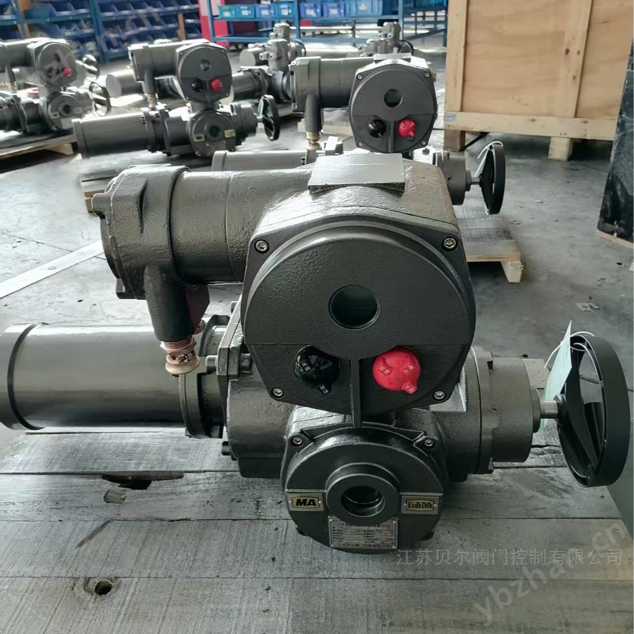
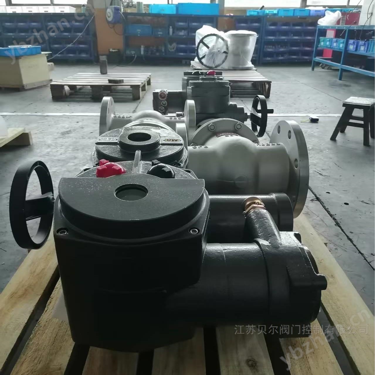
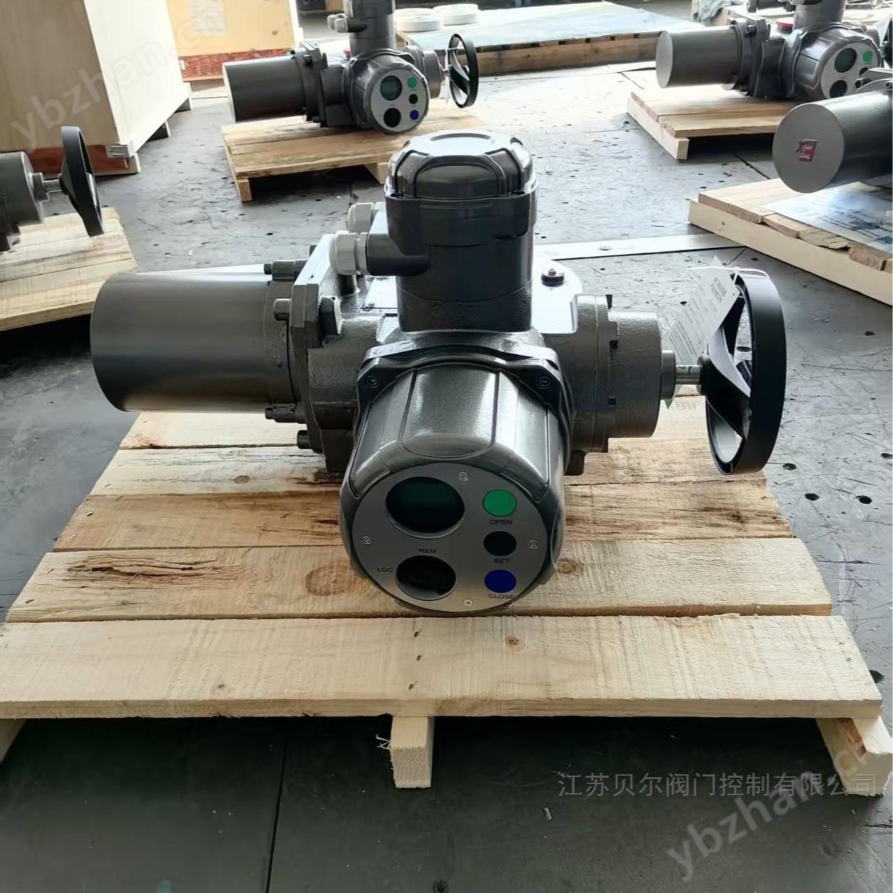
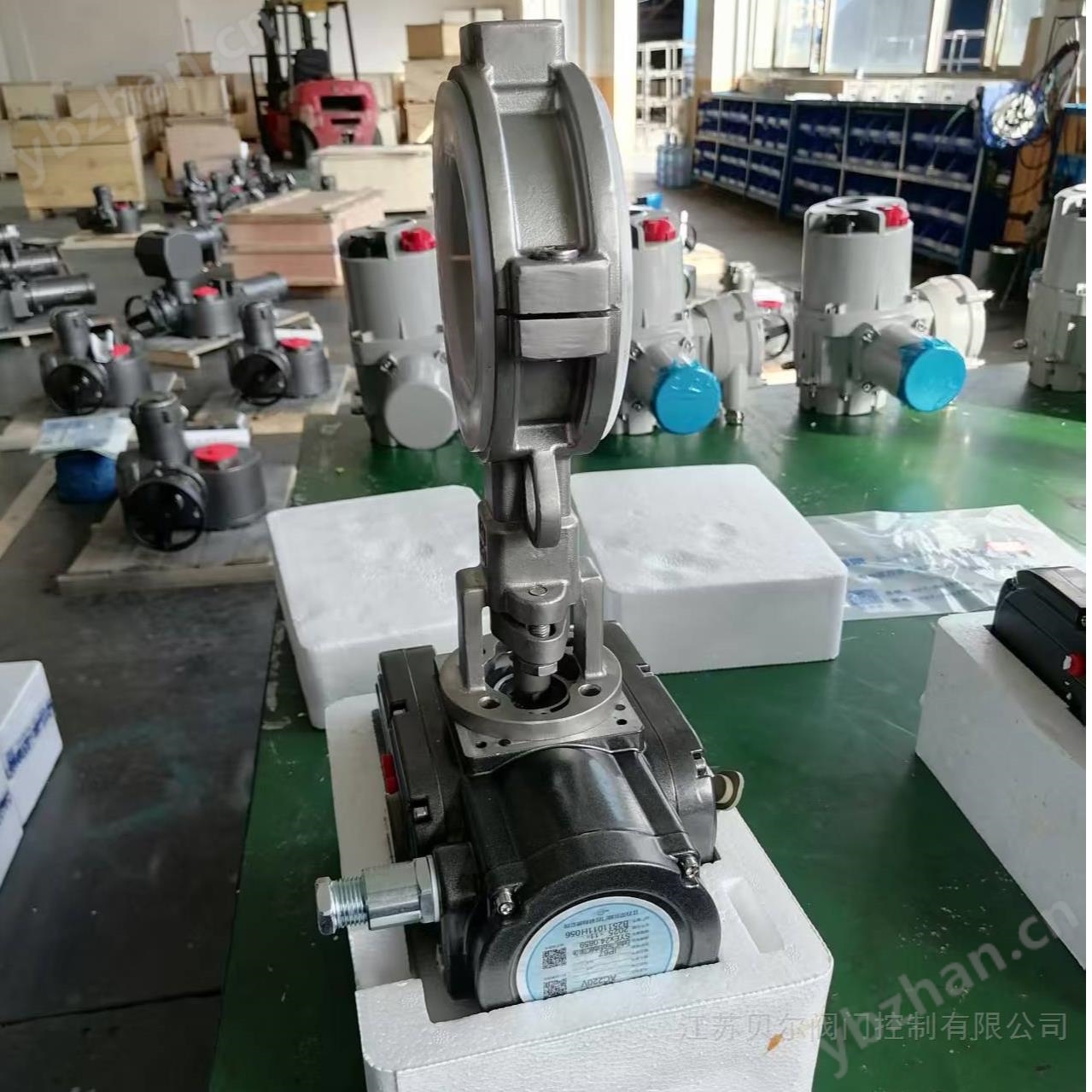
The intelligent coal safety integrated explosion-proof electric actuator for mining valves is a professional modification of the original ordinary explosion-proof valve electric device, also known as the ZB type explosion-proof valve electric device. Valves suitable for linear motion of opening and closing components, such as gate valves, globe valves, diaphragm valves, water gate valves, etc. After adding secondary deceleration, it can be used for butterfly valves, air doors, and air duct valves. Used for opening, closing, or regulating valves, it is a driving device that enables remote and centralized control of valves.
Mining valvesIntelligent coal safety integrated explosion-proof electric actuator
The explosion-proof valve electric device for mining is used in conjunction with the corresponding specialized KXBC explosion-proof control box for underground use.
The performance of the ZB series explosion-proof valve electric device not only complies with the provisions of JB/T8528-1997 "Technical Requirements for Ordinary Valve Electric Devices", but also complies with the provisions of GB3836.1-2000 "Electrical Equipment for Explosive Gas Environments Part 1: General Requirements", GB3836.2-2000 "Electrical Equipment for Explosive Gas Environments Part 2: Explosion proof Type" d '"and Q/320412BSK001-2007" Technical Conditions for Mining Valve Electric Devices ".
Explosion proof type: mining explosion-proof type.
Mining valvesIntelligent coal safety integrated explosion-proof electric actuatorWorking environment and main technical parameters
3.1 Power supply: Motor conventional voltage: 3807, 660 (special 1277, 2207, 4157, 4407, 480V, 11407), two-phase four wire or three-phase three wire; Control voltage: AC: 6V, 127, 247, 36V, 42V, 127V
DC: 67, 127, 247, 367, 487, 1107
Remote control: DC24V
3.2 Working environment:
3.2.1 The altitude shall not exceed 2000 meters;
3.2.2 Environmental temperature: -20~+402;
3.2.3 Relative humidity: Three 95% (+25 at 2 o'clock);
3.2.4 Coal mines with methane explosive gas;
3.2.5 Protection level: IP55
3.3 Work schedule: Short duration of 10 minutes.
Precautions for use
1The installation form of this electric actuator has no principle requirements, but the recommended installation form is when the motor is in a horizontal state and the electrical box cover is in a horizontal or vertical upward state, which is beneficial for lubrication, debugging, maintenance, and manual operation;
2During installation, the space required for maintenance and inspection personnel to disassemble each component should be ensured;
3The axial clearance between the tooth socket connected to the valve during installation shall not be less than1 ~2mm;
4When used for open stem valves, the extension of the valve stem should be checked to ensure that it matches the length of the valve stem sheath;
5During installation, disassembly, and debugging, the sealing surface, sealing components, and explosion-proof surface of the explosion-proof electric actuator should not be damaged, and anti rust oil should be applied to the explosion-proof surface;
6When disassembly is required, the manual handwheel should be rotated several times before proceeding with the valve slightly open;
7Before installation, check whether the explosion-proof mark on the nameplate is consistent with the installation environment;
8The grounding screw on the junction box must be reliably grounded with a grounding wire;
9The strength of the connecting screws between the electric device and the valve should be8.8Grade;
10When lifting electric devices, a reasonable lifting position should be selected to avoid falling, bumping, and other phenomena;
11Open the junction box, use a wrench to unscrew the compression nut of the cable entry device, firmly connect the cable to the terminal block in the junction box, confirm that there are no errors, cover the junction box with the top cover, and tighten the fastening screw. The terminal connection should be secure and follow the diagram10The method shown is to clamp the wire with an elbow. The junction box has4An introduction device,1One motor power cable is introduced, and three control cables are introduced. The power cables used must have a ground wire and be connected to the grounding terminal on the terminal block. The diameter specifications of the introduced cable are shown in the table5After connecting the wire, a tight sealing ring should be installed, and the Shore hardness of the sealing ring should be45~55Degrees, damages, and aging should be replaced promptly.