-
E-mail
lixin@yunjingtianhe.com
-
Phone
15666887396
-
Address
Room 206, Building 1, Weifang High tech Zone Optoelectronic Industry Accelerator (Phase I), No. 155 Optical Circuit, Weifang High tech Zone, Shandong Province
Product Categories
Shandong Tianhe Environmental Technology Co., Ltd

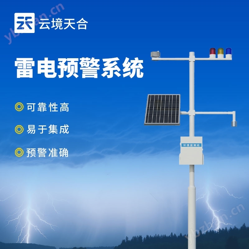
Lightning Warning System for Large Oil and Gas Storage Bases
NegotiableUpdate on 11/20
- Model
- Nature of the Manufacturer
- Producers
- Product Category
- Place of Origin
Overview
The lightning warning system for large-scale oil and gas storage bases is widely used in various places that require lightning protection, such as the power industry pushing warnings to substations and transmission line operation and maintenance teams, arranging personnel to evacuate outdoor work sites in advance, activating line lightning protection devices, and reducing line tripping and equipment burning caused by lightning. Aviation and transportation provide real-time warnings for airports, airlines, highways, ports, etc., assisting dispatch departments in adjusting flight takeoff and landing plans or suspending outdoor construction to avoid equipment failures causing urban functional interruptions. The petrochemical and hazardous chemicals industry has issued warnings to places such as oil depots, gas fields, chemical plants, and hazardous chemical warehouses, triggering
Product Details
Lightning Warning System for Large Oil and Gas Storage BasesWidely used in various places that require lightning protection, such as the power industry pushing warnings to substations and transmission line operation and maintenance teams, arranging personnel to evacuate outdoor work sites in advance, activating line lightning protection devices, and reducing line tripping and equipment burning caused by lightning. Aviation and transportation provide real-time warnings for airports, airlines, highways, ports, etc., assisting dispatch departments in adjusting flight takeoff and landing plans or suspending outdoor construction to avoid equipment failures causing urban functional interruptions. The petrochemical and hazardous chemicals industry sends warnings to oil depots, gas fields, chemical plants, hazardous chemical warehouses, and other places, triggering shutdown plans, stopping loading and unloading operations, closing outdoor valves, and preventing lightning from igniting flammable and explosive substances and causing explosions and fires.

1、 Product Introduction
Lightning Warning System for Large Oil and Gas Storage BasesIt is a fully digital electric field detection and lightning warning platform. Its core electric field detection structure is based on the principle of charge induction and developed using MEMS (Micro Electro Mechanical Systems) technology. It has no easily worn and movable mechanical components such as motors, and has outstanding advantages such as small size, low power consumption, high reliability, and easy integration. The system adopts electric field differentiation combined with threshold threshold optimization for lightning warning algorithm. Compared with the conventional threshold method, it is more likely to avoid false alarms caused by human interference (rainy/windy/snowy/dusty), further improving the accuracy of warning. The lightning warning system provides accurate warning, is easy to network, and is easy to install. It is mainly aimed at the application needs of atmospheric electric field detection and lightning local short-term warning in aerospace defense, meteorology, petroleum and petrochemical, power grid, scenic spots, mines, oil depots, military and other fields.
2、 Product composition
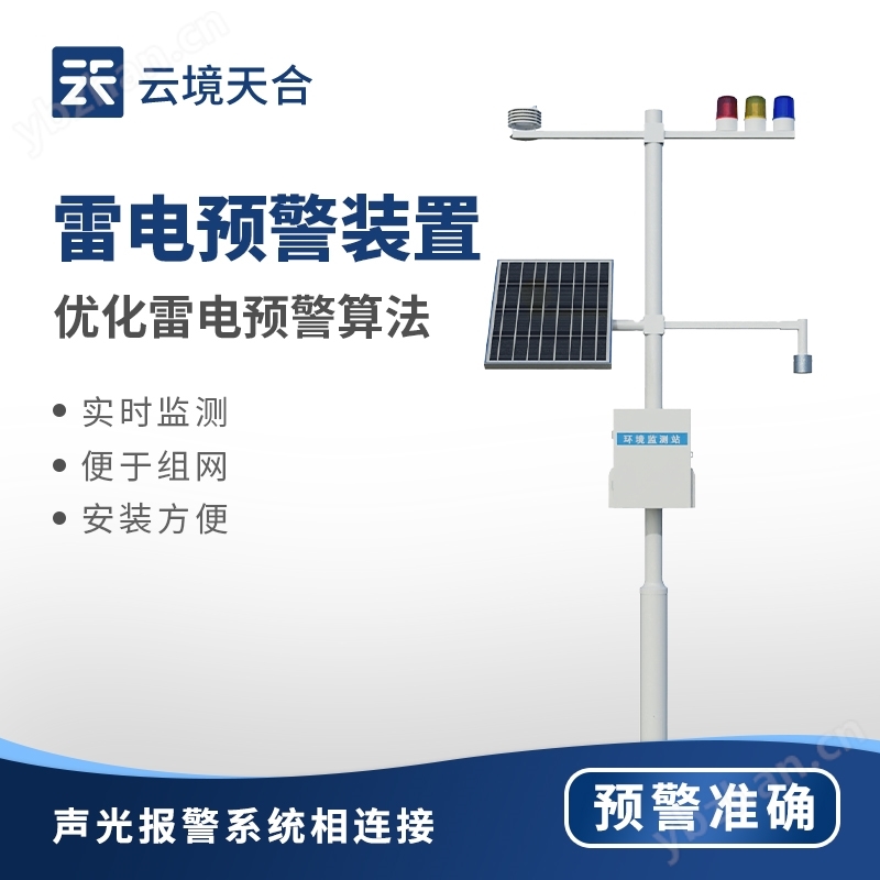
1. Lightning warning probe
2. Data processing host
3. Solar power supply system
4. Surge system
5. Grounding system
6. Air temperature, humidity, and atmospheric pressure sensors
7. Sound and light alarm level 3
8. Cloud data query and real-time display
3、 Product Features
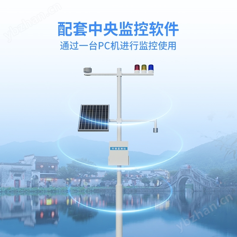
1. Users can connect the lightning warning system probe to the cloud server to achieve remote monitoring
2. By analyzing the data, make more accurate judgments on the strength and polarity changes of the thunderstorm electrostatic field
3. This system can be connected to the sound and light alarm system
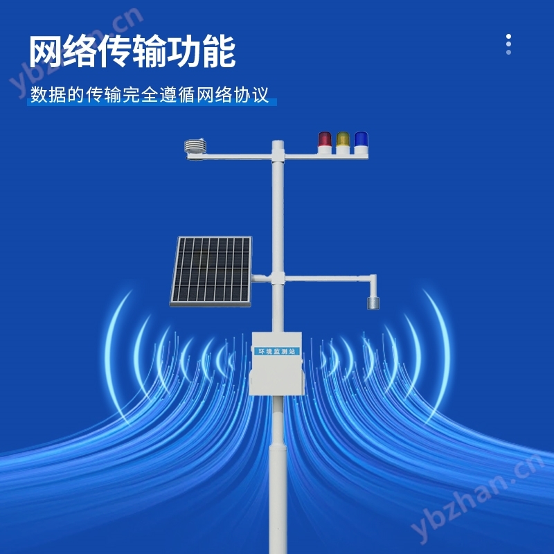
4. The system software has complete network transmission functions; The transmission of data follows network protocols
4、 Technical parameters
| device name | Lightning warning system |
| Electric field measurement range | -100kV/m~100kV/m |
| resolution | 0.1V/m |
| accuracy | ±0.001%F.S |
| Detection distance (radius) | 15KM |
| Total weight | 36KG |
| Sensor weight | 710g |
| input voltage | DC12V |
| power consumption | 12VDC( 2W@12V )(System) |
| size | 105 * 78mm (sensor); 3m (pole support) |
| Operating Temperature | -10 ℃~60 ℃ (sensor); -40 ℃~80 ℃ (controller) |
| Deployment location (indoor/outdoor) | outdoors |
| Shelf height | 2m (bracket) (sensor installation height 1.8m) |
| Management interface type | RS485 Modbus RTU (sensor); RS485 json/RS485 Modbus RTU (controller) |
| Alarm linkage (control) function | Level 3 warning |
| Number and types of data interfaces | 3 aviation sockets, 1. power supply, 2. RS485 json, 3. RS485 Modbus RTU |
| GPRS data traffic demand | 100M/month |
| External data frequency | 60s |
| Outbound Data Communication Protocol (Broadcast) | json |
5、 Installation precautions
1. Lightning warning probes should be installed on sunny days
2. Lightning warning probes should be installed outdoors without obstruction or surrounding obstructions
3. It shall not be installed at the exhaust outlet of the generator, next to the power pole, or under the high-voltage line
4. Under abnormal circumstances, when protruding from the ground, close to antenna poles or other equipment, the field strength and its test data may be interfered with
5. In wired mode, the wiring distance from the outdoor electric field meter probe to the indoor host is not recommended to exceed 100 meters
6. The equipment should have good grounding during use
6、 Installation steps
1. Take out the complete lightning warning system from the box
2. Fix the bracket to the designated installation position and secure it with bolts
3. Connect the lightning rod (optional) top grounding point to the grounding wire, and the other end of the grounding wire is introduced from the inside of the bracket and led out from the bottom hole of the bracket. After installing the grounding electrode and other grounding devices, connect the lightning rod grounding wire
4. Introduce the wires of the atmospheric electric field meter probe and the temperature, humidity, and pressure sensor from the inside of the bracket, lead them out through the hole in the middle of the bracket, and connect them to the main control box. There is an expansion box inserted into the main control box,
5. Fix the solar panel onto the bracket and connect the solar wires to the photovoltaic controller according to their colors
7. Connect the battery to the photovoltaic controller
8. Connect the control wires of the three color sound and light alarm lights to the alarm control module according to their respective colors
9. Contact after-sales service through the device number on the equipment box to obtain a login account
10. Open the computer and log in to the cloud platform through a browser (Google or Huawei Browser) to view data
Similar Product Recommend