-
E-mail
ziyingyeya@163.com
-
Phone
13501607526
-
Address
No. 3668 Bao'an Road, Jiading District, Shanghai, near Yongsheng Road
Product Categories
Shanghai Ziying Hydraulic Equipment Co., Ltd

Requirements for hydraulic system of traction device: Shanghai Hydraulic Design
NegotiableUpdate on 01/18
- Model
- Nature of the Manufacturer
- Producers
- Product Category
- Place of Origin
Overview
The hydraulic system of the traction device requires Shanghai Hydraulic Design. Our company can customize and produce non-standard hydraulic equipment such as hydraulic stations, hydraulic cylinders, hydraulic systems, hydraulic power units, etc. according to customer usage requirements. The equipment is located at 202 Zhenye Road, Dongjing Town, Songjiang District, Shanghai.
Product Details
The hydraulic system of the traction device requires Shanghai Hydraulic Design. Our company can customize and produce non-standard hydraulic equipment such as hydraulic stations, hydraulic cylinders, hydraulic systems, hydraulic power units, etc. according to customer usage requirements. The equipment is located at 202 Zhenye Road, Dongjing Town, Songjiang District, Shanghai.
Technical requirements for hydraulic drive system and its control
1. On site conditions:Provide 4 sets of oil quick plug interfaces with a pressure of 8-28MPa and a flow rate of 52-200L/Min on site, with a spacing of 4m between each set of quick plug interfaces.
2. Technical requirements:
The positioning accuracy of the vehicle body is 1mm.
2. There are two speed requirements: work in and fast forward. The work in speed should not be less than 17mm/s, and the fast forward speed should not be less than 30mm/s (for reference).
3. The traction system can achieve jog, continuous movement, and emergency stop.
4. Hydraulic cylinders and valve group seals should be used as backup.
5. The hydraulic drive system runs smoothly, without power impact or oil leakage.
6. The working mode of the hydraulic drive system is single group single step drive, which means that after walking, it will retract and support the next base to continue driving.
7. All indicators are the minimum indicators, and the margin can be selected according to the actual situation.
8. Use a handheld device to control the extension and contraction of the hydraulic cylinder.
3Overall Introduction
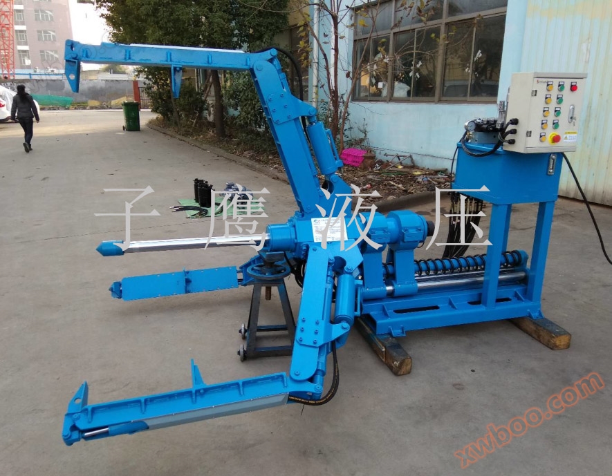
The traction device consists of two parts: main traction and auxiliary traction, which are separated and independently controlled. The main traction consists of two main push cylinders (mechanically synchronized), one small lifting cylinder, and auxiliary hydraulic and electrical components. The control method is: industrial remote control (with receiver)+intermediate relay+solenoid valve, as shown in Figure 1. The auxiliary traction is composed of one auxiliary pushing oil cylinder, and the control method is: fixed button+relay+solenoid valve.
4Main traction cylinder
The main drive system includes a hydraulic drive system behind the mass block support vehicle. Figure 2 is a schematic diagram of the overall structure, and the hydraulic drive system includes two parallel main push cylinders and one main lift cylinder.
4.1Main push cylinder:
- Effective travel: 650mm.
- The pushing and pulling force shall not be less than 30t.
- Two main hydraulic cylinders achieve rigid synchronization, and the main hydraulic cylinder should be able to withstand a certain lateral force.
- Outer diameter not exceeding 200mm
4.2Main lifting cylinder:
- Effective travel: 350mm.
- The pushing and pulling force shall not be less than 4.4t
5. Auxiliary traction oil cylinder:
The auxiliary traction cylinder includes an auxiliary pushing cylinder and an auxiliary lifting cylinder, as shown in Figure 3.
- Effective travel: 700mm.
- The pushing and pulling force shall not be less than 10t
6. Main traction working mode
When the main traction is working, the auxiliary traction does not work, that is, the auxiliary traction is always in a state where the auxiliary lifting cylinder lifts the auxiliary pushing cylinder.
6.1 Initial state
As shown in Figure 3, the main lifting cylinder and main pushing cylinder behind the mass block support vehicle are in a retracted state, that is, the pull rod is detached from the base.
6.2 Forward working mode
In the initial state, when the supporting vehicle moves forward (to the right), the main push cylinder is lowered and the push rod is pressed against the base; The main lifting cylinder piston rod extends, pushing the mass block to support the vehicle forward; At this point, it's over. Then the main thrust oil cylinder is partially retracted; Retract the main lifting cylinder and lift the main pushing cylinder; Retract the piston rod of the main push oil cylinder; At this point, complete one step. Then lower the main push cylinder and repeat the above steps to continue moving forward.
5.3 Backward working mode
To retreat, press the push-pull rod against the other side of the base and repeat the above steps.
6. Auxiliary traction working mode
When the auxiliary traction is working, the main traction does not work, that is, the main traction is always in a state where the main lifting cylinder lifts the main pushing cylinder.
6.1 Initial state
As shown in Figure 4, the auxiliary push cylinder is in the middle position and can be pushed forward by 300mm during movement.
6.2 Forward and backward working mode
In the intermediate state, when the supporting vehicle is moving backwards (to the left), the auxiliary push cylinder should be pushed forward by 300mm and fully retracted after being pushed into place.
more
Previous: None Next: None
Similar Product Recommend