-
E-mail
617795392@qq.com
-
Phone
15665728586
-
Address
Building 2, Research Building, Zone 3, Hanyu Jingu, High tech Zone, Jinan City
Product Categories
Jinan Fangjiang Power Technology Co., Ltd
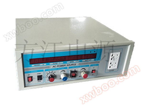
Single phase 0.5K1K variable frequency power supply
NegotiableUpdate on 10/19
- Model
- Nature of the Manufacturer
- Producers
- Product Category
- Place of Origin
Overview
Due to the inconsistent power grid indicators in different countries, the production and export of electrical products or the use of imported instruments require power sources to simulate the power grid conditions of different countries and ensure stability In the past, using generators for secondary frequency conversion resulted in high noise, poor stability, low efficiency, and large size, gradually being replaced by variable frequency power supplies. FJB variable frequency power supply is designed and manufactured specifically for the transformation, frequency conversion testing, and power supply of imported and exported electrical products. It can provide standard grid voltages and frequencies from around the world, with output voltages of single-phase (0-300V), three-phase (0-520V), and two gear settings for output voltage. The frequency (45-67Hz) is infinitely variable and the waveform is stable and pure, eliminating grid interference. It is suitable for transformer and frequency conversion testing of exported electrical products, as well as various precision tests in laboratories, metrology rooms, etc. In addition, the power supply comes with high-precision voltage, current, power, and frequency meters, integrating the source and meter, and has a high cost performance ratio Adopting Siemens original high-power IGBT module group design, reducing circuit complexity, improving product stability, reducing power loss, and continuously increasing single machine capacity. In addition, multiple ultra isolation transformers completely isolate the mains and load to increase the overall functionality of the machine.
Product Details
1. Overview:
Due to the inconsistent power grid indicators in different countries, the production and export of electrical products or the use of imported instruments require power sources to simulate the power grid conditions of different countries and ensure stability. In the past, using generators for secondary frequency conversion resulted in high noise, poor stability, low efficiency, and large size, gradually being replaced by variable frequency power supplies. Variable frequency power supply is designed and manufactured specifically for the transformation, frequency conversion testing, and power supply of imported and exported electrical products. It can provide standard grid voltages and frequencies from around the world, with output voltages (0-300V) and frequencies (45-65Hz) that are infinitely adjustable digitally. The waveform is stable and pure, eliminating grid interference. It is suitable for transformation and frequency conversion testing of exported electrical products, as well as various precision tests in laboratories, metrology rooms, etc. In addition, the power supply comes with high-precision voltage, current, power, and frequency meters, integrating the source and meter, and has a high performance price ratio Adopting Siemens original high-power IGBT module group design, reducing circuit complexity, improving product stability, reducing power loss, and continuously increasing single machine capacity. In addition, multiple ultra isolation transformers completely isolate the mains and load to increase the overall functionality of the machine.
This power supply inputs the voltage and frequency of the AC power grid, and after internal inversion conversion from AC to DC and DC to AC, it generates a very stable and pure sine wave on its own.
2. Choose the capacity method:
Pure resistive load power supply capacity=1.1 × load power
Rectifying load power supply capacity=load current peak coefficient/1.5 * load power
Pure inductive load power supply capacity=load starting current/1.5 * rated current * load power
Mixed loads should be selected comprehensively according to the proportion of different loads
3. Product model description:
|
Single phase model |
capacity |
Three phase model |
capacity |
|
FJB11-0.5K |
500VA |
FJB13-3K |
3KVA |
|
FJB11-1K |
1KVA |
FJB13-6K |
6KVA |
|
FJB11-3K |
3KVA |
FJB13-10K |
10KVA |
|
FJB11-5K |
5KVA |
FJB33-15K |
15KVA |
|
FJB31-10K |
10KVA |
FJB33-20K |
20KVA |
|
FJB31-15K |
15KVA |
FJB33-30K |
30KVA |
|
FJB31-20K |
20KVA |
FJB33-45K |
45KVA |
|
FJB31-30K |
30KVA |
FJB33-60K |
60KVA |
|
FJB31-60K |
60KVA |
FJB33-100K |
100KVA |
|
FJB31-100K |
100KVA |
FJB33-200K |
200KVA |
|
Note: Single phase maximum capacity: 200KVA |
Note: The maximum capacity of three-phase is 800KVA |
||
4. Technical indicators (conventional products):
Single phase series:
|
Machine model |
FJB11-0.5k |
FJB11-1k |
FJB11-3k |
FJB11-5k |
FJB11-10k |
FJB31-15k |
FJB31-20k |
FJB31-30k |
FJB31-45k |
FJB31-60k |
FJB31 |
||||||||||
|
capacity |
500VA |
1KVA |
3KVA |
5KVA |
10KVA |
15KVA |
20KVA |
30KVA |
45KVA |
60KVA |
100KVA |
||||||||||
|
Circuit method |
IGBT/SPWM Pulse Width Modulation Method |
||||||||||||||||||||
|
Input |
voltage |
220V±10% |
380V±10% |
||||||||||||||||||
|
phase number |
single-phase |
three-phase four-wire |
|||||||||||||||||||
|
frequency |
50Hz/60Hz±10% |
||||||||||||||||||||
|
output voltage |
Low range: 0-150V; High range: 0-300V |
||||||||||||||||||||
|
output frequency |
Fixed frequency: 50Hz/60Hz/100Hz/200Hz, FM: 47-63Hz |
||||||||||||||||||||
|
output current |
high-end |
2.2A |
4.5A |
13.6A |
22.7A |
45A |
68A |
90A |
136A |
204A |
272A |
455A |
|||||||||
|
low-end |
4.5A |
9A |
27.2A |
45.4A |
90A |
136A |
180A |
272A |
409A |
544A |
910A |
||||||||||
|
Voltage stabilization rate |
≤1% |
||||||||||||||||||||
|
frequency stability |
Fixed frequency ≤ 0.01%, frequency modulation ≤ 0.1% |
||||||||||||||||||||
|
Waveform distortion degree |
THD≤2% |
||||||||||||||||||||
|
reaction time |
≤2ms |
||||||||||||||||||||
|
efficiency |
≥94% |
||||||||||||||||||||
|
Electricity meter display |
LED LCD can display frequency, voltage, current, power, and power factor in four digits |
||||||||||||||||||||
|
contact method |
RS485 Ethernet port optional |
||||||||||||||||||||
|
protection function |
Complete overvoltage, overcurrent, overtemperature, overload, short circuit protection and automatic alarm |
||||||||||||||||||||
|
Insulation reactance |
500Vdc 20MΩ |
||||||||||||||||||||
|
voltage-resistant insulation |
1800Vac/5mA/1 minute |
||||||||||||||||||||
|
cooling method |
Fan cooling |
||||||||||||||||||||
|
Operating Temperature |
-15℃―+45℃ |
||||||||||||||||||||
|
relative humidity |
0-90% (non condensing state) |
||||||||||||||||||||
|
altitude |
≤2000m |
||||||||||||||||||||
|
Dimensions (width x depth x height) mm |
430×420×135 |
440× |
350× |
400× |
450×830×1000 |
500×1000×1100 |
520×1260×1370 |
||||||||||||||
Three phase series:
|
Machine model |
FJB13-6k |
FJB13-10k |
FJB33-30k |
FJB33-45k |
FJB33-60k |
FJB33 -100k |
FJB33 -150k |
FJB33 -300k |
FJB33-450k |
FJB33 -600k |
|||||
|
capacity |
6KVA |
10KVA |
30KVA |
45KVA |
60KVA |
100KVA |
150KVA |
300KVA |
450KVA |
600KVA |
|||||
|
Circuit method |
IGBT/SPWM Pulse Width Modulation Method |
||||||||||||||
|
input |
voltage |
220V±10% |
380V±10% |
||||||||||||
|
phase number |
single-phase |
three-phase four-wire |
|||||||||||||
|
frequency |
50Hz/60Hz±10% |
||||||||||||||
|
output voltage |
Phase voltage: Low range: 0-150V, High range: 0-300V |
||||||||||||||
|
Line voltage: Low range: 0-260V, High range: 0-520V |
|||||||||||||||
|
output frequency |
Fixed frequency: 50Hz/60Hz, FM: 47-63Hz |
||||||||||||||
|
output current |
high-end |
9A |
15.2A |
45A |
68A |
90A |
151A |
227A |
455A |
683A |
909A |
||||
|
low-end |
18A |
30.4A |
90A |
136A |
180A |
302A |
none |
||||||||
|
Voltage stabilization rate |
≤1% |
||||||||||||||
|
frequency stability |
Fixed frequency ≤ 0.01%, frequency modulation ≤ 0.1% |
||||||||||||||
|
Waveform distortion degree |
THD≤2% |
||||||||||||||
|
reaction time |
≤2ms |
||||||||||||||
|
efficiency |
≥94% |
||||||||||||||
|
Electricity meter display |
LED LCD can display frequency, voltage, current, power, and power factor in four digits |
||||||||||||||
|
protection function |
Complete overvoltage, overcurrent, overtemperature, overload, short circuit protection and automatic alarm |
||||||||||||||
|
Insulation reactance |
500Vdc 20MΩ |
||||||||||||||
|
contact method |
RS485 Ethernet port optional |
||||||||||||||
|
voltage-resistant insulation |
1800Vac/5mA/1 minute |
||||||||||||||
|
cooling method |
Fan cooling |
||||||||||||||
|
Operating Temperature |
-15℃-+45℃ |
||||||||||||||
|
relative humidity |
0-90% (non condensing state) |
||||||||||||||
|
altitude |
≤2000m |
||||||||||||||
|
Dimensions (width x depth x height) mm |
400×660× 700 |
450×830×1000 |
500×1000×1100 |
520×1260×1370 |
550×1380×1560 |
1500×850×1850 |
2000×1200×1900 |
3260×830×2260 |
|||||||
5. Installation precautions:
1. Does the model of the variable frequency power supply match the ordered model and capacity.
2. Has the variable frequency power supply been damaged due to improper transportation. If there is, please do not connect the power supply.
Before inputting power into the power cord, the specifications of the power supply should be determined to avoid damage to the variable frequency power supply.
4. Variable frequency power supplies have different installation standards depending on their capacity and input voltage. Please choose the appropriate wiring method according to the capacity and input voltage, and pay special attention to whether the wire diameter meets the specifications.
5. When wiring, please refer to the "Electrician Regulations" for selection. Pay attention to the input end of the variable frequency power supply, avoid sharing the same switch with other devices, and try to be as close as possible to the mains power supply head.
6. Please use O-type terminals for wiring terminal construction. When wiring the input and output terminal blocks, be sure to connect the power cord and tighten the screws to avoid poor contact and prevent electric shock.
7. Please turn off the power when wiring, and it is strictly prohibited to work with live wires. Pay attention to safety.
8. When wiring, pay attention to whether all terminal plugs and sockets are loose to avoid the danger of poor conductivity.
6. Panel Description:
Schematic diagram of power panel

Description of Analog Variable Frequency Power Supply Panel
|
serial number |
Name |
Instructions |
Function |
|
1 |
power switch |
|
Control the input and output of the mains power. Place this key in the "on" position to indicate that the power is turned on; This key is placed in the "off" position, indicating that the power is turned off. |
|
2 |
Start/Stop button |
|
Place this key in the start position to enter the running state; Place this key in the stop position to enter standby mode. |
|
3 |
Output frequency selector knob |
|
When in standby mode, rotating this knob can quickly switch the output frequency to 50Hz, 60Hz, 100Hz, 200Hz, and adjust (frequency modulation). |
|
4 |
Frequency (FM) adjustment knob |
|
When adjusting (frequency modulation) the output frequency selector knob, rotating clockwise in the output state can quickly increase the output frequency; Turning counterclockwise can quickly reduce the output frequency. |
|
5 |
Output voltage high/low gear conversion button |
|
When in standby mode, press this button to select high output voltage; Press this button to select low output voltage. |
|
6 |
Output voltage adjustment knob |
|
When in operation, rotating this knob clockwise within the voltage selection range can quickly increase the output voltage; Turning this knob counterclockwise can quickly decrease the output voltage. |
|
7 |
Power/power factor conversion button |
|
Press this button to switch the display between the actual load power and the power factor value. |
|
8 |
Power factor indicator light |
|
When the light is on, window 9 displays the load power factor |
|
9 |
Power indicator light |
|
When the light is on, window 9 displays the load power unit in watts |
|
10 |
Power/Power Factor Display Window |
LED display |
Display actual load power or power factor during operation |
|
11 |
Current display window |
LED display |
Display the actual output current value during operation. |
|
12 |
Voltage display window |
LED display |
Display the actual output voltage value during operation. |
|
13 |
Frequency display window |
LED display |
Display the actual output frequency value during operation. |
|
14 |
output socket |
|
Power output 6-pole socket |
7. Operation steps:
1) Confirm whether the input power supply is within the specifications (see page 8 of the technical parameters of this machine for details).
2) Power on
Press the power switch, and the LED display will be in standby mode.
● Frequency modulation: The frequency of this power supply is set in two ways: 1) Fixed frequency mode: The reference frequency is obtained by dividing it by a crystal oscillator,
Good stability, with a fixed frequency of 50/60Hz selected through a switch; 2) FM mode: first, turn the frequency switch to the leftmost or rightmost end, and then adjust the "FM" knob to adjust the output frequency to the desired value. The positions of the toggle switch and frequency knob can be found on the control panel.
Press the START/STOP button to adjust the voltage knob so that the output voltage corresponds to the load input voltage. The inverter inside the machine will start working, and the output indicator light will turn on; The digital display shows the output voltage, output current, output frequency, load power, and power factor. If the power supply is used for the first time, please use an external voltmeter to check whether the voltage at the output terminal is consistent with the displayed value on the panel meter, and confirm before adding the load.
During operation, the machine may emit slight high-frequency sounds, which is a normal phenomenon.
3) Shutdown
When the START/STOP button is pressed, the inverter stops working and the machine stops outputting. During operation, if a malfunction occurs, the internal protection circuit will automatically shut down the inverter, stop outputting, and issue an audible and visual alarm.
If the machine is not in use for a long time, please disconnect the input circuit breaker/power switch.
Note:When selecting the output frequency and switching between high and low output voltage, it must be done in standby mode.
8. Common troubleshooting:
This machine is only for maintenance by electricians. Please pay attention to the internal high voltage. Non professionals are not allowed to open the machine door for maintenance without authorization.
When the machine cannot operate smoothly, please shut it down first and check the following steps:
|
Phenomenon |
inspection method |
troubleshooting |
|
No input power supply |
|
|
|
Output power interruption |
|
|
|
No output voltage |
|
Dangerous silk.
|
|
The output frequency, voltage, current, and wattmeter display "0000" while the buzzer sounds an alarm. |
|
|
|
Temperature too high |
|
|
|
Urgently call for repair |
|
Please advise:
|
9. Technical parameters of this machine:
1. Input:
Voltage: 220V ± 10% Frequency: 50Hz ± 10%
2. Output:
Voltage: 0-150V, 0-300V Frequency: 50Hz, 60Hz, 100Hz, 200Hz, 45-65Hz
Voltage stability accuracy: ≤ 1%
Frequency stability accuracy: ≤ 0.01%
Waveform distortion: ≤ 2%
3. Overload capacity: Strong overload capacity, instantaneous current can withstand twice the rated current
4. Protection: equipped with overcurrent, high temperature, short circuit, instantaneous power failure protection and warning devices
5. Working conditions:
Environmental temperature: -15 ℃~45 ℃
Relative humidity: ≤ 95% (25 ℃)
6. Operation display mode: Voltage (V), Frequency (Hz), Current (A), Power (W) 4 window measurement display
7. Applicable load: No type limitation, can adapt to completely unbalanced loads, but the motor and rectifier loads need to be rated down for use.
After-sales service
From the date of self sale of our company's power products, if there is a malfunction due to quality issues, free repairs will be provided within one year, and only cost fees will be charged after one year; Special models of products can be customized.


