-
E-mail
hi@tempinst.com
- Phone
-
Address
No. 130 Chang'an Road, Yuyao City, Ningbo City, Zhejiang Province
Product Categories
Yuyao Jingchuang Instrument Co., Ltd

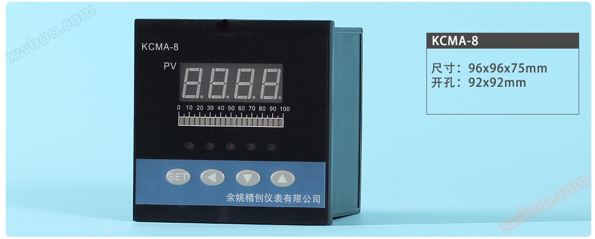
Thermal resistance PT100 input 4-channel alarm relay light column display instrument
NegotiableUpdate on 09/10
- Model
- Nature of the Manufacturer
- Producers
- Product Category
- Place of Origin
Overview
Function Overview: Working Environment: Temperature -10~60 ℃; Humidity ≤ 90% RH ● Input adopts a precise and stable digital calibration system, supporting multiple thermocouple and thermistor specifications, with a maximum resolution of 0.1 ℃
Product Details
- Function Overview:
- Working environment: temperature -10~60 ℃; Humidity ≤ 90% RH
The input adopts a precise and stable digital calibration system, supporting multiple thermocouple and thermistor specifications, with a maximum resolution of 0.1 ℃.
The operation method of humanized design is easy to learn and use.
The anti-interference performance meets the requirements of electromagnetic compatibility (EMC) under harsh industrial conditions.
This instrument adopts maintenance free technology of automatic zero adjustment and digital calibration. If it exceeds the tolerance during metrological verification, it can be corrected by parameters
By default, it comes with four sets of relay alarms and can independently set alarm values.
- Input signal:
- Choose one of the following signals, fixed at the factory:
CU50(-50.0~150.0)、PT100(-199.9~600.0)、K(-50.0~1300)、 - E(-50.0~800.0)、 J(-50.0~999.9)、T(-50.0~400.0)、
- 0-10mA、4-20mA、0-10V、1-5V、NTC
- Control output:
- By default, it comes with four alarm relays and can be controlled in a positional manner (upper and lower limit control).
- Alarm output:
- Default with four-way alarm relay (special instructions required): '0' has no alarm; '1' upper limit alarm; '2' lower limit alarm;
- Appearance size:
- Length x Width x Depth (mm) A: 96 x 96 x 75 x 92 x 92;
D:72×72×75 68×68; E:48×96×75 44×92; F:96×48×75 92×44;

S: 80 x 160 x 85 x 76 x 156.
| Other functions: | Equipped with light column display, the range of light column display and digital tube display can be independently set separately. | Instrument wiring diagram: | Built in parameters of the instrument: |
|---|---|---|---|
| 0 | Parameter Code | symbol | name |
1 |
Instructions |
AL-1 | Alarm 1 setting |
2 |
The first alarm setting value, please refer to parameter ALP1 for the alarm method |
HY-1 | Alarm 1 time difference |
| 3 | Return difference setting for alarm contact output (single-sided return difference) | AL-2 | Alarm 2 setting |
| 4 | The second alarm setting value, please refer to parameter ALP2 for the alarm method | HY-2 | Alarm 2 times differential |
| 5 | Return difference setting for alarm contact output (single-sided return difference) | AL-3 | Alarm 3 setting |
| 6 | The third alarm setting value, please refer to parameter ALP3 for the alarm method | HY-3 | Alarm 3 times differential |
| 7 | Return difference setting for alarm contact output (single-sided return difference) | AL-4 | Alarm 4 setting |
| The fourth alarm setting value, please refer to parameter ALP4 for alarm mode | |||
| 8 | HY-4 | Alarm 4 times differential | Return difference setting for alarm contact output (single-sided return difference) submenu |
9 |
LOCK |
combination lock |
When LOCK=18, it is allowed to modify all parameters |
10 |
When LOCK ≠ 18, it is prohibited to modify all parameters |
SC |
Sensor error correction |
| 11 | When the measurement sensor causes errors, this value can be used to correct them | DP | decimal place When the instrument is used for voltage or current input, its display upper limit, display lower limit, decimal point position, and unit can be freely set by the manufacturer or user. When dp=0, the decimal point will not be displayed in units, and when dp=1-3, the decimal point will be displayed in tens, hundreds, and thousands, respectively. |
| 12 | P-SH | Display upper limit | |
| 13 | When the instrument is used for voltage and current input, the digital display shows the upper and lower limit set values (this menu is not displayed for inputs other than voltage and current) | The user can independently set the range of instrument digital display. | P-SL Display lower limit |
| 14 | G-SH | Light column display upper limit | |
15 |
The upper and lower limits of the instrument light column display determine the display range of the light column. |
The display range is determined by P-SH P-SL |
G-SL |
16 |
Light column display lower limit |
PF |
filter coefficient |
17 |
For the first-order lag filtering coefficient of the instrument, the larger its value, the stronger its resistance to instantaneous interference, but the response speed lags behind. Its value should be relatively small for pressure and flow control, and relatively large for temperature and liquid level control. |
ALP1 |
|
18 |
Definition of Alarm Method 1 |
'0' has no alarm; '1' upper limit alarm; '2' lower limit alarm |
|
| 19 | ALP2 | Definition of Alarm Method 2 | |
| 20 | ALP3 | Definition of Alarm Method 3 | ALP4 |
| 21 | Definition of Alarm Method 4 | ADDR | Mailing Address |
Similar Product Recommend