-
E-mail
335086021@qq.com
-
Phone
15988121817
-
Address
New City Industrial Zone, Jianggan District, Hangzhou
Product Categories
Hangzhou Aolituo Instrument Technology Co., Ltd

Ultrasonic level gauge ZY-100
NegotiableUpdate on 11/20
- Model
- Nature of the Manufacturer
- Producers
- Product Category
- Place of Origin
Overview
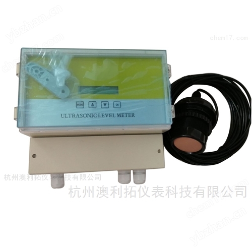
The ultrasonic level gauge ZY-100 is a digital level instrument controlled by a microprocessor. In measurement, ultrasonic pulses are emitted by sensors (transducers), and the sound waves are reflected by the liquid surface and received by the same sensor. They are converted into electrical signals by piezoelectric crystals, and the distance from the sensor to the measured liquid surface is calculated based on the time between the emission and reception of the sound waves.
Product Details

Ultrasonic level gauge ZY-100
Range: 0-20m (large range can be customized, blind zone: 0.35m~0.5m);
Distance measurement accuracy: 0.5%;
Power supply voltage: DC12V, DC24V/AC220V. The lightning protection device is built-in;
Host display: LCD display (resolution 1mm);
Analog output: 4-20mA (optional 1-4 relay outputs);
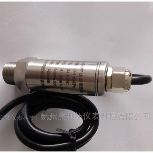
Sensor pressure resistance:<0.1MPa; IP67;
Digital output: RS485, Modbus protocol or customized protocol;
Environmental temperature: -40 ℃ to 80 ℃;
IISplit wave level gaugeinstrument installation
1. Host size and installation method (Figure 1, Figure 2)

Host installation method: a. Indoor installation can be directly fixed on the wall with a pendant, wall mounted installation.
b、 Outdoor installation: A stainless steel protective box needs to be added to prevent excessive aging of the LCD display screen.
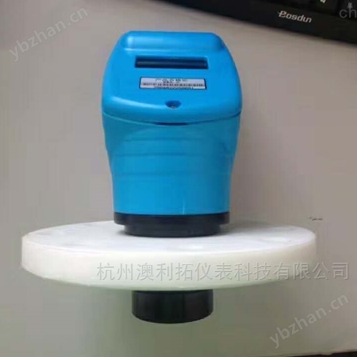
2. Sensor size and installation method
Sensor size (Figure 3)

Note: The sensor size can be customized according to the requirements of the on-site working conditions.
Installation method
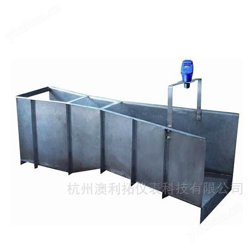
Installation of water tank (usually using L-shaped bracket installation method, Figure 4)
Principle: (All installation methods are the same)
a、 The installation position of the sensor should be kept as close as possible to the inner wall of the pool (>50cm or more) to prevent sound waves from hitting the protruding points on the inner wall of the pool and causing multiple echoes; The probing surface should be kept absolutely parallel to the measured water surface;
b、 The installation height should be less than the factory range of the instrument;
c、 The highest water level refers to the range of the upper limit that the instrument can measure;
d、 The instrument cannot measure the water level within the blind zone (0.35-0.5mm) range;
e. L refers to the actual water level height; H refers to the height (distance) of the air.

Installation of arched roof storage tank (generally using flange installation method, Figure 5)
Principle: (Same installation method as the water tank)
Note: When installing sensors on dome shaped storage tanks, it is best not to install them at the highest point of the tank arch (as shown in Figure ①). This installation position can easily cause multiple echoes of sound waves; The correct position should be installed at 2/3 or 1/2 of the tank radius.

Installation of flange with connecting pipe (Figure 6)
Principle: (Same installation method as the water tank)
Note: When the sensor is installed on the flange connecting pipe, the acoustic emission surface of the probe should be lower than the bottom of the flange connecting pipe height, so that the acoustic emission surface extends into the top of the storage tank;

Installation with feeding port (Figure 7)
Principle: (Same installation method as the water tank)
Note: When installing sensors in storage tanks or water tanks with feeding ports, they should avoid the feeding port. To prevent data fluctuations caused by sound waves hitting the feed water column. The ① in the picture is the correct installation position.

Installation of waveguide method (Figure 8)
Principle: (Same installation method as the water tank)
Note: When the sensor is installed in a stirred reactor or storage tank, a bypass pipe needs to be installed to reduce the impact of liquid level fluctuations on measurement; When the sensor is installed in the working condition where the measuring space is relatively narrow or the liquid level foam layer is relatively thick, it is necessary to install a guided wave tube. It is recommended that the diameter of the bypass pipe and waveguide pipe be greater than DN100, and the specific selection should be based on the actual measurement range on site. The larger the range, the larger the pipe diameter.

Please download the PDF for detailed instructions!
Similar Product Recommend