-
E-mail
18752476625@163.com
-
Phone
18751941608
-
Address
Room 1304, Building A1, No. 216 Pu Liu North Road, Getang Street, Jiangbei New District, Nanjing City
Product Categories
Nanjing Haohai Marine Technology Co., Ltd
Underwater acoustic communication algorithm verification experimental platform
NegotiableUpdate on 11/20
- Model
- Nature of the Manufacturer
- Producers
- Product Category
- Place of Origin
Overview
The modulation and demodulation program and algorithm used in the VST-ACTest underwater communication algorithm verification experimental platform are implemented by MATLAB programming. The MATLAB program is called through Labview and the data acquisition card is controlled to trigger the underwater communication equipment; At the receiving end, communication signal data acquisition is completed through hydrophones and data acquisition cards, and real-time signal display and offline data processing are completed through VC programs.
Product Details
VST-ACTestUnderwater acoustic communication algorithm verification experimental platformThe modulation and demodulation program and algorithm used are implemented by MATLAB programming, and the MATLAB program is called through Labview to control the data acquisition card to trigger the underwater acoustic communication equipment; At the receiving end, communication signal data acquisition is completed through hydrophones and data acquisition cards, and real-time signal display and offline data processing are completed through VC programs.
Main hardware parameters:
(1) Underwater sound power amplifier: 190 dBuPa@1m (High power model); The corresponding maximum output voltage amplitude shall not be less than 900Vpp@22KHz The output signal amplitude is continuously adjustable;
(2) Transducer frequency band: 20K-30KHz (or customized frequency band according to user requirements);
(3) Hydrophone: Supports 4 inputs;
(4) AD/DA unit: NI4431 acquisition card
(5) Power supply: Equipped with dual lithium batteries for power supply (the host and underwater acoustic transmitter are independently powered), with a standby time of 8 hours; The transmission signal of the underwater acoustic signal power amplifier shall not be less than 1000 frames (typical OFDM communication signal); Support external power supply.
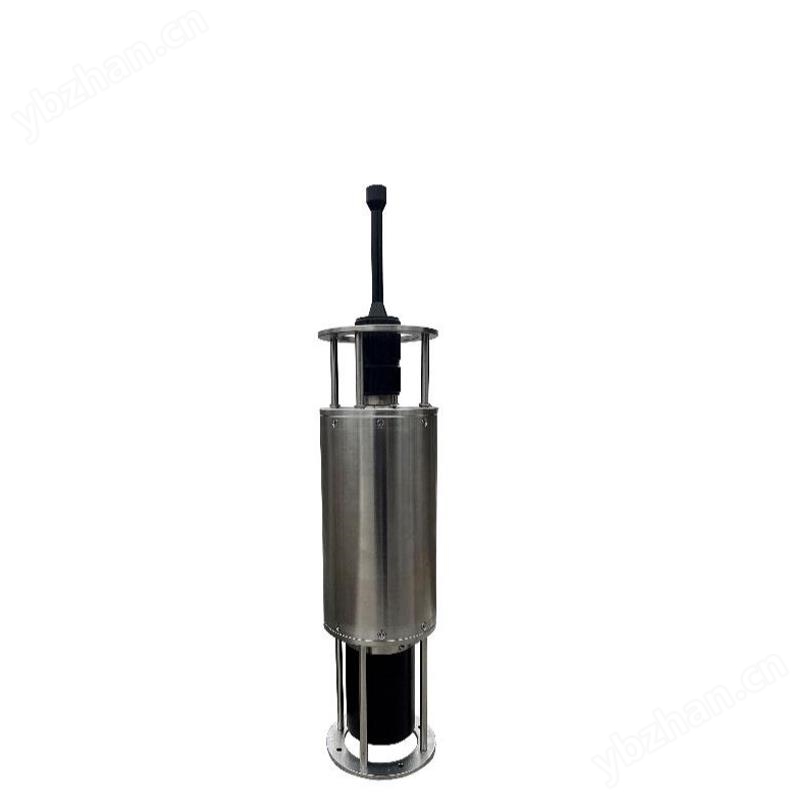
(6) Built in MFSK example application, maximum communication distance: 8-10Km (30 meter shallow water conditions).

Figure 1. Appearance of the Underwater Acoustic Communication Test Platform
technical indicators
1. Underwater acoustic signal power amplifier
Parameter performance:
Operating frequency range: 20k-30kHz, matched with WBT-22 transducer;
Power supply voltage: 24-36V single power supply DC power supply;
Output signal: 190 dBuPa@1m (High power model);
2. Digital/Analog Conversion Module
ADC sampling accuracy of 24 bits, sampling rate of 102.4Ksps;
3. Transmitting transducer
Operating frequency range: 20kHz-30kHz
Sending voltage response:>143dB ± 3dB@22kHz
Horizontal beamwidth: 360 °;
Vertical beamwidth 55 °± 3 ° @ 22kHz
Cable length: 10 meters
4. Receive hydrophones
Parameter performance:
Operating frequency range: 20Hz-100kHz Low
Frequency reception sensitivity:>-200dB
Cable length: 15 meters
Platform software: Labview+Matlab
Function introduction: The modulation and demodulation program and algorithm used in underwater acoustic communication are implemented by MATLAB programming. The MATLAB program is called through Labview and the data acquisition card is controlled to trigger the underwater acoustic communication equipment; At the receiving end, communication signal data acquisition is completed through hydrophones and data acquisition cards, and real-time signal display and offline data processing are completed through VC programs.
The main system adopts the Windows 10 operating system
Features: This platform can test and develop various modulation and demodulation signals. The development environment based on Matlab is conducive to the testing and rapid implementation of complex algorithms, and can also complete real underwater acoustic signal testing through real hardware. Support the transmission and reception of multiple underwater acoustic modulation signals; Capable of signal playback and analysis, including signal time-domain display, frequency domain display, and signal constellation display. (Provide MATLAB source code for some modulation schemes)
User Introduction: 1. Sender: Select the modulation method according to the requirements, call the modulation algorithm written in MATLAB to modulate the signal, and at the same time, produce a WAV file from the modulated signal. Return to LABVIEW to select the generated WAV file and send it, which can achieve continuous transmission, and the user can control the number of transmissions.

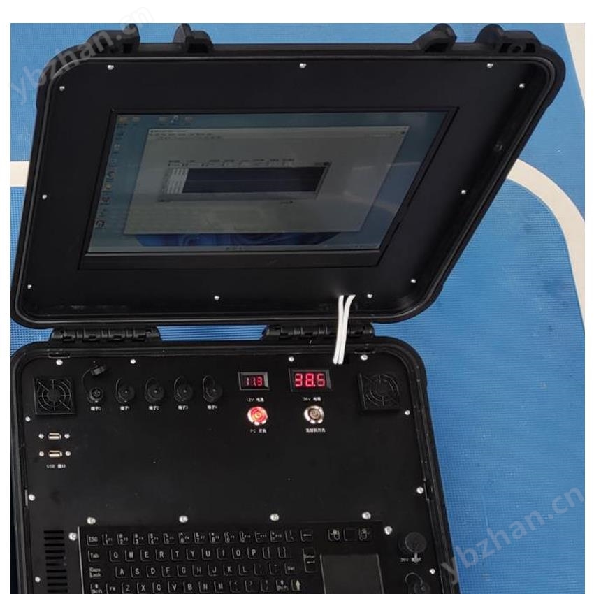
Figure 2. Signal Transmission Control Panel
2、 The offline demodulation interface of the receiving end now mainly includes the following two aspects: firstly, it can collect and save data; After stopping the collection, you can select the data you want to demodulate from the folder where the files are currently saved

Figure 3. Real time signal reception display interface
Similar Product Recommend