-
E-mail
flora187@126.com
-
Phone
18926849868
-
Address
Building 1, No. 2 Shuishi Road Street, Jiujiang, Changping Town, Dongguan City, Guangdong Province
Dongguan Saisi Testing Equipment Co., Ltd
Cold and hot shock test chamber - the difference between three box and two box types
Date: 2025-09-29Read: 11
In reliability testing, cold and hot shock testing is known as the "quick and fatal test", which can expose potential defects of the product in a short period of time, such as solder joint cracks, structural cracking, packaging failure, etc.
And the equipment structure is the core variable of the thermal shock test effect. There are currently two common structures in the industry:
Two box thermal shock test chamber; Three box thermal shock test chamber
Many customers ask when selecting equipment:
Is three boxes more advanced? "" Is there a standard for conversion time? "" Which one is my product suitable for
This article will comprehensively interpret the differences between these two structures from four aspects: standard definition, equipment structure, technical parameters, and application industries, and provide selection recommendations based on international standards (GB/T, IEC, MIL-STD).
One Standard definition of thermal shock test
The thermal shock test belongs to the temperature change test (Test N) defined in GB/T 2423.22-2012 and IEC 60068-2-14:2009, and is divided into:
Test Na: Rapid temperature changes with specified conversion time; Test Nb: Temperature change with specified rate of change
Its core technical actions include:
Two temperature zones: high temperature and low temperature;
Quickly switch between temperature zones (transfer); Maintain sufficient exposure time in each temperature zone to complete stress loading.
II The definition of conversion time t ₂ and exposure time t ₁ in the standard
🔹 Exposure time (t ₁):
According to Section 7.2.3 of IEC 60068-2-14:2009:
The exposure time t ₁ should be set in conjunction with the sample's heat capacity, with recommended values including 15 minutes, 30 minutes, 1 hour, 2 hours, and 3 hours. '
👉 It is common for industrial products to take 15-30 minutes.
🔹 Conversion time (t ₂):
Section 7.2.5 of IEC 60068-2-14:2009 defines:
T ₂ refers to the transfer of the sample from one temperature zone to another (applicable to two box structures), or to the switching, movement, and residence time of hot/cold air flow in a single chamber at room temperature. '
👉 The standard recommendation is that t ₂ should not exceed 3 minutes.
MIL-STD-883H (Method 1010) specifies a specific requirement for JUN microelectronic device testing: "Conversion time ≤ 10s. However, if the basket size is too large, the conversion time may exceed 10s.
III Analysis of the Working Principles of Two Structures
✅thermal shock chamberTwo box typestructure
The sample tray moves up and down or left and right between the high and low temperature chambers to achieve thermal conversion.
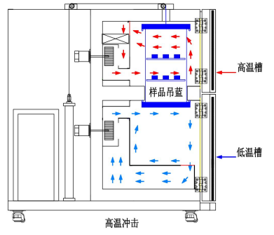
thermal shock chamberTwo box typeTechnical specifications:
model |
SEL-A |
SEL-B |
SEL-C |
Basket size |
40×40×30 |
50×50×30 |
60×60×30 |
outer box dimensions |
136×192×205 |
146×230×220 |
162×232×220 |
Upper limit of preheating temperature |
+60.00 ℃~+200.00 ℃ (about 30 minutes) |
||
Lower limit of pre cooling temperature |
R. T~-80.00 ℃ (about 60 minutes) |
||
Impact temperature range |
-65.00℃/ -55.00℃/ -40.00℃~+150.00℃ |
||
temperature fluctuation |
≤ 1 ℃ (≤± 0.5 ℃, expressed according to GB/T5170-1996) |
||
temperature deviation |
≤±2℃(-65℃~+150℃) |
||
Temperature Uniformity |
≤2 |
||
Temperature recovery time |
≤5min |
||
Convert time |
<5Sec |
||
controller |
LCD touch screen PLC controller |
||
Cooling method |
Mechanical compression binary cascade refrigeration method |
||
Operation mode |
Program running+constant running |
||
outer box material |
Cold rolled steel plate electrostatic spraying |
||
safety protection |
Leakage, short circuit, overheating, water shortage, motor overheating, compressor overpressure, overload, current protection |
||
power supply voltage |
AC380V 50Hz three-phase four wire+grounding wire |
||
thermal shock chamberThree box typestructure

thermal shock chamberThree box typeTechnical specifications:
Model (CM) |
SET-A |
SET-B |
SET-C |
SET-D |
SET-G |
|
internal dimensions |
40×35×35 |
50×50×40 |
60×50×50 |
70×60×60 |
80×70×60 |
|
external dimensions |
140×165×165 |
150×190×175 |
160×190×185 |
170×240×195 |
180×260×200 |
|
structure |
Three box type (pre cooling box) (preheating box) (testing box) |
|||||
Damper Device |
Mandatory air device valve |
|||||
Inner box material |
SUS # 304 stainless steel |
|||||
outer box material |
Cold rolled steel plate electrostatic spraying |
|||||
Freezing system |
Mechanical compression binary cascade refrigeration method |
|||||
Convert time |
<10Sec |
|||||
Temperature recovery time |
<5min |
|||||
temperature deviation |
±2℃ |
|||||
cooling method |
water cooling |
|||||
dwell time |
30 min |
|||||
temperature range |
preheating temperature |
+60~200℃(40min) |
||||
High temperature impact |
+60~150℃ |
|||||
Pre cooling temperature |
+20℃~-80℃(70min) |
|||||
Low temperature shock |
-10℃~-40℃/-55℃/-65℃ |
|||||
temperature sensor |
JIS RTD PT100 Ω× 3 (Platinum Sensor) |
|||||
controller |
LCD touch screen PLC controller |
|||||
Control method |
By relying on integral saturation PID, fuzzy algorithm balanced temperature control P.I.D+P.W.M+S.S.R |
|||||
Standard Configuration |
1 set of illuminated glass windows, 2 sample racks, and 1 test lead hole are attached |
|||||
safety protection |
Leakage, short circuit, overheating, water shortage, motor overheating, compressor overpressure, overload, overcurrent protection |
|||||
power supply voltage |
AC380V 50Hz three-phase four wire+grounding wire |
|||||