-
E-mail
18752476625@163.com
-
Phone
18751941608
-
Address
Room 1304, Building A1, No. 216 Pu Liu North Road, Getang Street, Jiangbei New District, Nanjing City
Nanjing Haohai Marine Technology Co., Ltd
Briefly describe the standardized operation process of DVL Doppler velocimeter
Date: 2025-08-21Read: 8
In marine surveying, underwater robot (ROV/AUV) navigation, water flow monitoring, and geological investigation, DVL Doppler velocimeter utilizes acoustic Doppler effect to measure the three-dimensional motion velocity and navigation distance of underwater vehicles relative to the bottom or water body in real time. It is the core sensor for achieving high-precision underwater positioning and autonomous navigation. It emits an acoustic beam (usually a four beam configuration) towards the seabed, receives the frequency changes of the reflected signal, and calculates the velocity components in all directions. To ensure reliable data and avoid misoperation, DVL Doppler velocimeter must follow scientific and standardized operating procedures.
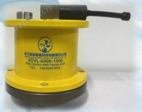
Step 1: Equipment inspection and installation positioning
Before use, check if the casing is intact and if there are no cracks or attachments on the surface of the transducer. Confirm that the cable interface is well sealed and there are no signs of water ingress. Firmly install the DVL on the bottom of the hull, ROV frame, or measuring rod, ensuring that the transducer is facing vertically or obliquely towards the seabed (depending on the working mode) to avoid interference from bubble zones. The installation angle deviation needs to be recorded for subsequent data correction.
Step 2: Parameter Setting and Mode Selection
Set key parameters through supporting software or control panel:
Working mode: Select "Bottom Tracking" (for near seabed velocity measurement and positioning) or "Water Tracking" (for measuring relative water layer velocity);
Range and frequency: Select the appropriate acoustic frequency based on the water depth (low frequency for deep water, high frequency for shallow water);
Data output format: Set NMEA, ASCII, or binary protocols to match navigation system requirements.
Step 3: System self-test and initialization
After power on, the instrument automatically executes a self-test program to check the signal strength of each beam, internal clock, and sensor status. Confirm that all beam echoes are good (signal-to-noise ratio SNR>15dB). Perform Zero Velocity Update in a stationary state to eliminate zero drift.
Step 4: Start measurement and real-time monitoring
After the device moves with the carrier, it begins to emit sound waves and receive echo signals. Real time monitoring of signal quality, velocity vector, and operating mode of each beam through software interface. Ensure stable locking of the seabed in bottom tracking mode and continuous and stable flow data in water tracking mode.
Step 5: Data recording and synchronous output
Enable data recording function to store raw speed, attitude, timestamp and other information in internal memory or external computer. If used for integrated navigation, it is necessary to ensure time synchronization between DVL and inertial navigation system (INS) (such as PPS synchronization), and output high-frequency velocity correction.
Step 6: Homework completion and equipment maintenance
After the measurement is completed, stop data recording, power off, and retrieve the DVL Doppler velocimeter. Immediately rinse the casing and transducer with fresh water to remove salt and sediment. Check if the sealing ring is aging, apply lubricating grease and store it properly in a drying oven.