-
E-mail
13714836101@163.com
-
Phone
13714836101
-
Address
Building B, No. 3 Third Road, Yangyong Industrial Zone, Songgang Street, Bao'an District, Shenzhen
Product Categories
Shenzhen Ruitaier Technology Co., Ltd

Electronic cigarette comprehensive testing machine
NegotiableUpdate on 02/19
- Model
- Nature of the Manufacturer
- Producers
- Product Category
- Place of Origin
Overview
Electronic Cigarette Comprehensive Testing Machine 1. Product Introduction: This machine is used to test electronic cigarettes and e-liquids. It adopts a cylinder piston suction method and determines whether the electronic cigarette is qualified by setting the corresponding smoking duration, smoking volume, and smoking frequency. It is suitable for low-power electronic cigarettes
Product Details
Electronic cigarette comprehensive testing machine
1、 Product Introduction:
This machine is used to test electronic cigarettes and e-liquids. It adopts cylinder piston suction and determines whether the electronic cigarette is qualified by setting the corresponding smoking duration, smoking volume, and smoking frequency. It is suitable for low-power electronic cigarettes.
Specifications
workstation |
1workstation |
Aspiration |
Cylinder piston type (using 1 cylinder) |
Smoking volume |
100ML (The supplier shall ensure that the set volume and actual consistency error do not exceed 1ml |
duration |
1-9.9 Seconds(The supplier shall ensure that the corresponding set parameter values are achieved under a single port volume of 50-150ml |
Interval between each mouth |
1-999 Seconds |
Number of smoking ports |
1-999s |
power |
Stepper motor (6N/M)+PLC |
Cylinder push-pull mechanism |
ball screw |
Touch screen counter |
Technology can be set, reaching the set number of times automatically |
Smoke concentration test |
Smoke concentration range: 0-99% (calibratable) |
special function |
The following process can be set up at once: (automatic volume control) For example, set 60ml per sip for 3 seconds with a 5-second interval between each sip, for a total of 300 puffs, with a 10 minute interval between every 50 puffs. Current voltage curve display, USB data saving and printing. |
Display and control mode |
Touch screen+PLC+self written program |
power supply |
1∮、AC220V |

The tail rectangle of the suction flow chart of the smoking machine. When measuring, it should be confirmed that the suction capacity meets the requirement of 17, and a (1000 ± 50) Pa pressure drop standard component should be connected in series in the air path between the smoking machine suction port and the measuring device. The typical flow chart without sample suction is shown in Figure 1. In Figure 1, the area V1+V3 enclosed by the curve when the airflow velocity increases (t0~t1) and decreases (t2~t3) shall not exceed 10% of the total suction capacity of the graph V1+V2+V3, and the maximum airflow velocity should be between 18.17ml/s and 20.17ml/s. The duration of the stable period of maximum airflow velocity (t1~t2) should not be less than 2.4 seconds. The inflection points of the rising and falling parts of the flow chart should not be more than one point, and there should be no reverse airflow at any point.
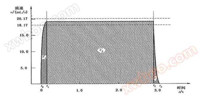
Explanation:
T0- the time when the airflow velocity starts to increase due to suction; T1- the time when the airflow velocity reaches its maximum; T2- the time when the airflow velocity begins to decrease due to the cessation of suction; T3- the time when the airflow velocity drops to zero; V1- the area enclosed by the rising segment of airflow velocity over time; V2- the area enclosed during the period when the airflow velocity reaches its maximum and remains stable; V3- the area enclosed by the decreasing segment of airflow velocity over time;
27. Use a "suction engine" to create suction;
28. The precision syringe (engine) driven by a stepper motor and controlled by a computer will provide accurate volume and suction port shape diagrams, with two available shapes: ISO sine curve and square wave. The tail rectangle of the suction flow chart of the smoking machine. When measuring, it should be confirmed that the suction capacity meets the requirement of 17, and a (1000 ± 50) Pa pressure drop standard component should be connected in series in the air path between the smoking machine suction port and the measuring device. The typical flow chart without sample suction is shown in Figure 1. In Figure 1, the area V1+V3 enclosed by the curve when the airflow velocity increases (t0~t1) and decreases (t2~t3) shall not exceed 10% of the total suction capacity of the graph V1+V2+V3, and the maximum airflow velocity should be between 18.17ml/s and 20.17ml/s. The duration of the stable period of maximum airflow velocity (t1~t2) should not be less than 2.4 seconds. The inflection points of the rising and falling parts of the flow chart should not be more than one point, and there should be no reverse airflow at any point.

Similar Product Recommend


