-
E-mail
info@bominte.com
-
Phone
13568882605
-
Address
No. 98 Tiancai Road, Gaoxin West District, Chengdu City, Sichuan Province
Product Categories
BOMIT PTE. LTD.
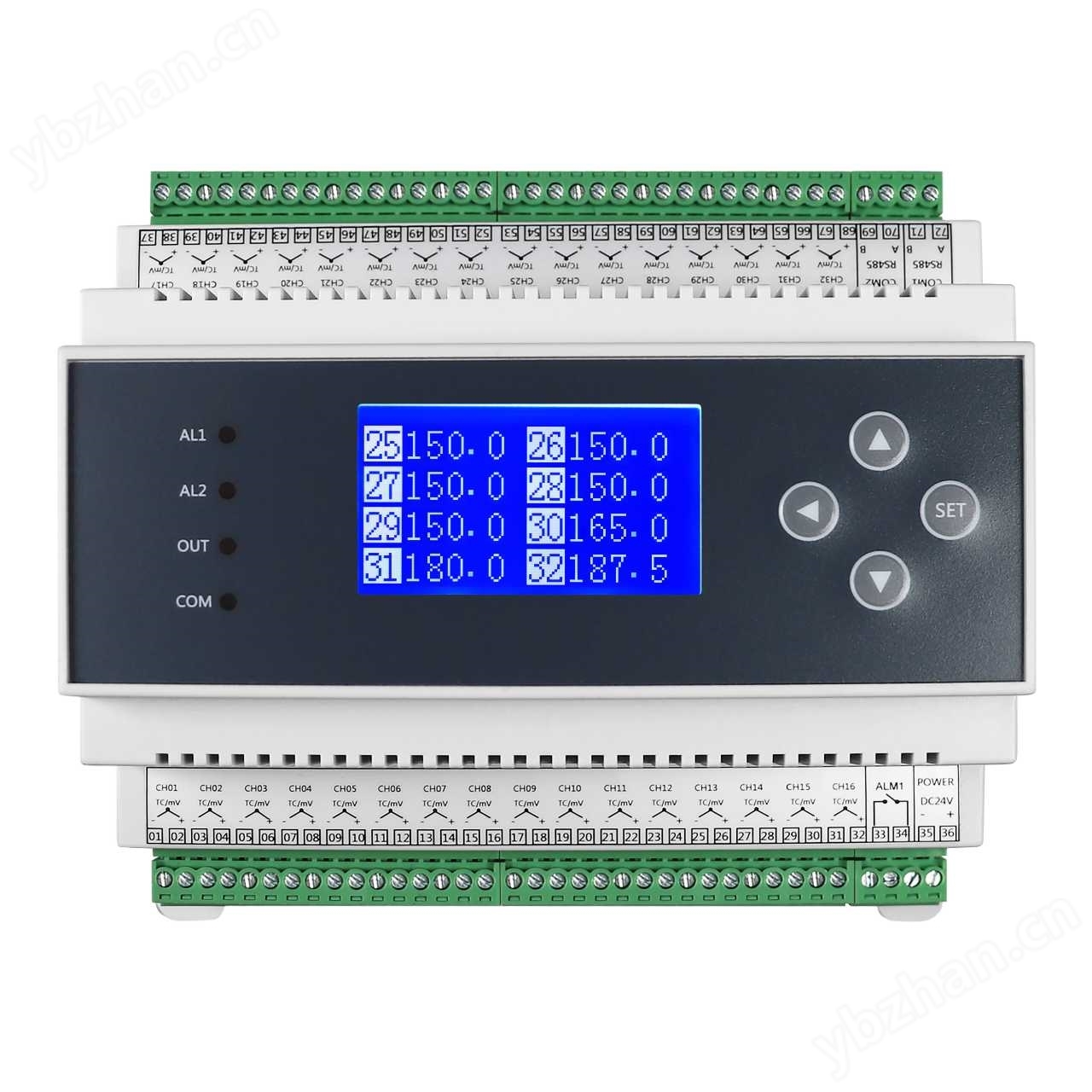

Multi channel isolated thermocouple acquisition
NegotiableUpdate on 09/21
- Model
- BMT6213
- Nature of the Manufacturer
- Producers
- Product Category
- Place of Origin
Overview
Multi channel isolated thermocouple acquisition, power/communication/input isolation. Each channel is isolated from each other, with an isolation voltage of 400V. Multiple ADs are collected in parallel, and all channels are refreshed in 2 seconds. Each channel input is equipped with overvoltage protection. LED display/wide temperature LCD Chinese and English operation display. The default 60 minute timed screen shutdown function reduces energy consumption. Equipped with buttons for convenient on-site debugging and setting by users. Two independent isolated lightning protection RS485 interfaces, standard MODBUS-RTU communication protocol. The wide range power supply is DC10-30V, and the power supply with rectifier bridge design can also work normally when connected in reverse.
Product Details
BMT6213 Multi channel isolated thermocouple acquisitiondevice
1、 Functional Features
Multi channel input, power/communication/input isolation, isolation voltage 1200V.
Each channel is isolated from each other, with an isolation voltage of 400V.
Multiple AD parallel acquisition, refresh all channels in 2 seconds.
Each channel input is equipped with overvoltage protection.
LED display/wide temperature LCD Chinese and English operation display.
The default 60 minute timed screen shutdown function reduces energy consumption.
Equipped with buttons for convenient on-site debugging and setting by users.
Two independent isolated lightning protection RS485 interfaces, standard MODBUS-RTU communication protocol.
The wide range power supply is DC10-30V, and the power supply with rectifier bridge design can also work normally when connected in reverse.
Equipped with self recovery insurance overcurrent protection and surge overvoltage protection.
DIN35 rail installation method.
IIMulti channel isolated thermocouple acquisitionMain technical indicators

3、 Terminal wiring

32 channel thermocouple mV signal or DC0-5V/10V wiring diagram
4Product Selection
Multi channel isolation collectorBMT6213-□□-□□□-□□-□ (M212)
①② ③④⑤ ⑥⑦ ⑧⑨

Note: 1. Each channel input type can be set separately. When ordering as a thermocouple, it can be set to 0-100mV and can be connected to a shunt.
2. The selection must be complete, and any functions that are not selected must also be filled in with code. Example of selection: BMT6213-T07-R0T0SS-0D-32 (M212)
3. Terminals 69 and 70COM2 can be used as slave devices for reading measurement values by the upper computer, and can also be connected to BMT6240 relay outputs or BMT6241 analog mA/V outputs.
5、 Operating instructions
(1) The key functions of the instrument panel are touch sensitive keys, please do not press them hard when using. In the off screen state, pressing any button can wake up the display.

(2) Parameter settings
In working mode, the instrument displays multiple channel measurement values simultaneously. Press and hold the SET button for about 1 second to enter the password verification screen. In the set state, display parameter prompt information and set values. If there is no button operation for about 60 seconds during the setting process, it will automatically exit the setting state and enter the running state. After setting a parameter, press the SET key to confirm and enter the next parameter setting state. During the setup process,Press and hold the ◄ key for about 2 seconds to return to the previous parameter setting state.


6、 Communication instructions
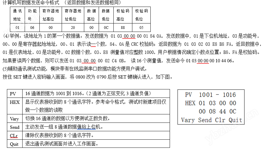
(1) This product is equipped with an RS485 interface for direct communication with a computer. The RS485 standard communication distance is 1.5km and can be connected to multiple instruments. The RS232 standard communication distance is 15m, and only one instrument can be attached. The TXD, RXD, and GND of the RS232 interface are respectively connected to the second, third, and fifth pins of the computer serial port. The data format consists of 1 start bit, 8 data bits, and 1 stop bit, and the checksum can be set. To avoid communication conflicts, the instruments are all in listening mode. The computer sends a command to a certain instrument at a specified address, and then waits for a period of time for the instrument to respond. After the instrument receives the correct command, it sends out the data. After sending, the instrument is in listening mode again. In the same system, instrument addresses cannot be the same, and baud rates must be consistent.
(2) Adopting the standard Modbus RTU communication protocol, using the 03, 04, and 06 function numbers. When using the configuration software touch screen, select a PLC with standard Modbus or Modicon (XX Kang) device, Modbus RTU address type, function number 3X or 4X can be used, register address starts from the first, data is a signed 16 bit integer, and when using Configuration King registers (i.e. 4x001, 4x000), other configuration software may start from 3x001 or 3x000. Users need to handle the decimal places according to their actual situation. It is recommended for user programming to define signed integer data, or by calculation. When the data is greater than 0X7FFF (decimal 32767), subtract the data from 65536 and then take a negative value. For example, if the communication transmission data is 0XFF9C (decimal 65436), 65536-65436=100, then take a negative value of -100. Professional algorithms can also use reverse addition 1. For long integer data such as cumulants, the data value is equal to high-order x 65536+low order, or the data type can be selected as long integer (Long), and the system will automatically calculate the cumulant. Register 4x1024 is a single precision floating-point number type for measurement values, following standard IEEE754, such as 0x42CAFBCF corresponding to 101.4918 (see also advanced parameter settings for four byte arrangement order that can be set).


7、 Alarm instructions
This instrument can be equipped with one or more alarm settings, and each channel can be set with alarms or multiple channels can share a set of alarm parameters for common alarms. Using two parameters of alarm value hysteresis to avoid frequent relay actions. In addition, advanced passwords have alarm delay function.
Upper limit alarm: If the measured value is higher than the alarm value, it will be in an alarm state. If the measured value is lower than the alarm value minus the difference value, the alarm state will be released;
Lower limit alarm: If the measured value is lower than the alarm value, it will be in an alarm state. If the measured value is higher than the alarm value plus the hysteresis value, the alarm state will be released;
Turn off alarm value: Prohibit alarm. The alarm status values of each channel can be read through communication.
8、 Warranty
If it is a manufacturing quality problem caused by the factory, the instrument will be repaired free of charge from the date of leaving the factory. If the damage is caused by improper storage and use, the repair cost will be charged. The warranty period is eighteen months.
9、 Frequently Asked Questions and Answers
1. For thermal resistance thermocouples, the instrument is designed for the full range of the sensor, and the upper and lower range parameters are invalid.
2. The signal types listed in the input signal type comparison table are all supported by the instrument. Special input signals need to be customized, such as WRe325, WRe526, PT1000, and thermistor.
4. When the sensor displays - HH -, check if the wiring is correct, verify if the thermocouple mV value/mA/V is normal, and check if the sensor type matches the input signal type set for the parameters. When using a thermocouple, if there is a short circuit at the input end, the corresponding channel will display the ambient temperature.
5. The temperature measurement principle of a thermocouple is to generate a potential difference. Insulation treatment should be done on site to prevent the potential of the measured object from being introduced into the acquisition instrument, or an isolated input acquisition instrument should be selected.
6. When communication is not available, check that the wiring is correct; The communication converter is functioning properly; The RS485 interface has a voltage of approximately 1.5V; Related parameter address baud rate checksum; The computer reads one (or eight) data and views the received data format on the auxiliary communication test function screen. If it is garbled, the two communication wires can be exchanged (reversing the communication wires will not damage the interface).
Similar Product Recommend


