-
E-mail
396852987@qq.com
- Phone
-
Address
No. 89 Science Avenue, Zhengzhou High tech Industrial Development Zone
Product Categories
Zhengzhou Quanzi Neng Electronics Co., Ltd

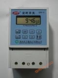
QZN-WK20 Intelligent Temperature Controller
NegotiableUpdate on 11/04
- Model
- Nature of the Manufacturer
- Producers
- Product Category
- Place of Origin
Overview
Instructions for QZN-WK20 Intelligent Temperature Control Switch I. Functional Features: The QZN-WK20 intelligent temperature control switch has stable performance, easy setting, beautiful and reasonable appearance, and flame retardant shell that meets safety requirements; This switch uses imported industrial grade chips as the core to measure temperature, and three high brightness red LED digital displays the temperature value, ensuring stable and reliable operation
Product Details
QZN-WK20Manual for Intelligent Temperature Control Switch
one、Features
QZN-WK20 Intelligent Temperature Control SwitchStable performance, easy setup, beautiful and reasonable appearance, and flame retardant shell that meets safety requirements; This switch uses imported industrial grade chips as the core to measure temperature, with three highlighted red positionsLEDDigital display temperature value, stable and reliable operation.Within the temperature measurement range(-The load can be switched on and off according to the temperature range and control mode set by the user (20 ℃~+120 ℃). The temperature parameters set by the user are stored in the chip, which is not affected by power outages and does not lose data during power outages. There are four different temperature control modes available, suitable for both heating and cooling control, which can meet the needs of the vast majority of application scenarios. Forward heating is suitable for electric heaters, electric ovens, electric incubators, electric water heaters, over temperature protection, etc., while reverse cooling is suitable for air conditioning refrigeration, exhaust ventilation, etc.Reminder: Before using the temperature control switch for the first time, it is necessary to select and set a temperature control mode, otherwise it will not work properly. For specific instructions, please refer to [Temperature Control Mode]Settings]Chapter!
2、 Related parameters
1. Rated voltage: 220V/50Hz; 2. Maximum load power: 3000W; 3. Measurement display temperature range: -20~120 ℃
4. Temperature control range: -20~120 ℃ 5. Temperature error ≤ ± 0.50 ℃~± 0.80 ℃
6. Display resolution: 0.1 ℃ (decimal places are not displayed for temperatures below -9.9 ℃ and above 99.9 ℃); 7. Shell material: high flame retardant engineering plastic
8. Installation method: Terminal wiring (three fixing methods: guide rail, suction wall, and hanging) 9. Dimensions: 115 * 75 * 55mm
10. Individual weight: 400 grams; 11. Type and wiring length of temperature sensor: Thermal sensitive, high temperature resistant, waterproof, standard with 8 meters
3、 Switch panel button diagram and wiring diagram


4Temperature control mode setting:In the temperature display state,Press and hold the [Add] and [Subtract] keys simultaneously for more than 5 seconds without releasing themEnter the working mode transition state and display'P_'Flashing, press[addend]Key or[subtrahend]The key is inP1-P2-P3-P4Adjust between them according to the table below to the working mode that suits you, and then press[Settings]keySimply return to the temperature measurement status. (Factory default set to P3 mode)
|
working mode
|
Control relationship*
|
Additional notes
|
|
P1
Single limit control heating type
|
When measuring values<The switch is turned on when setting the value, and when measuring the value>The switch is disconnected when setting the value
|
Suitable for simple low-power heating control, only one temperature limit needs to be set.
For example: small electric heaters, water heaters, etc
|
|
P2
Single limit control cooling type
|
When measuring values>The switch is turned on when setting the value, and when measuring the value<The switch is disconnected when setting the value
|
Suitable for simple low-power cooling control, only one temperature limit value needs to be set.
For example: small cooling devices, fans, etc
|
|
P3
Dual limit control heating type
|
When measuring values<When the lower limit is set, the switch is turned on<measured value<When the upper limit is set, the switch state remains unchanged. When the measured value is>The switch is disconnected when the upper limit is set
|
Suitable for complex and high-power heating control, it is necessary to set upper and lower temperature limits to avoid frequent starting and stopping of control equipment and extend its lifespan.
For example: industrial heating equipmentElectric oven, electric incubation
|
|
P4
Dual limit control cooling type
|
When measuring values>When the upper limit is set, the switch is turned on. When the lower limit is set, the switch is turned on<measured value<When the upper limit is set, the switch state remains unchanged. When the measured value is<The switch is disconnected when the lower limit is set
|
Suitable for complex and high-power cooling control,It is necessary to set upper and lower temperature limits to avoid frequent starting and stopping of control equipment and extend its lifespan.
For example: industrial cooling equipment breeding, cold storage
|
*noteThe size of the measured value of the control relationship refers to the integer of the measured temperature value, excluding decimal places (the set value only has integer digits).
5、 Operation Settings
1,Set upper and lower temperature limitsIn the temperature display state, press the [Set] button once to enter the upper limit temperature setting after displaying H, and the upper limit temperature display will flash. Press the [Add] or [Subtract] button to adjust the upper limit temperature value, and then press the [Set] button again to enter the lower limit temperature setting after displaying L, and the lower limit temperature display will flash. Similarly, press the [Add] or [Subtract] button to adjust the lower limit temperature value. After setting is complete, press the [Set] button again to return to the temperature measurement state. Explanation: If the temperature control working modes P3 and P4 are selected, when setting the upper and lower temperature data, regardless of their order and numerical size, the system will automatically set the higher numerical value as the upper limit value and the lower numerical value as the lower limit value. If the temperature control working modes P1 and P2 are selected, the display will show - -, and only one temperature value needs to be set.
2,Automatically exit the set stateIf there is no normal operation to exit the setting state during the data setting process, and no button is pressed for 30 seconds in the middle, the system will automatically exit the setting state and return to the temperature measurement state. At the same time, the data for this setting operation will be automatically saved.
6、 Output delayThe output port has added a judgment delay of about 2 seconds. If every measurement result within 2 seconds meets the action requirements of the output port, the output port will actually execute the action. Otherwise, it will not execute. The purpose is to avoid output port misoperation caused by fluctuations such as lightning small induction, large equipment start and stop, etc.
Fault safety measures:If the sensor experiences an open circuit fault, the display will immediately show 'HHH'. If the sensor and its leads are short circuited, the display will immediately show 'LLL'. In order to prevent adverse consequences that may occur after the sensor is open or short circuited, the control output port will be closed first.
7、 Other
1. The use of temperature control switches and the absence of corrosive gases on site; Sensors should not be corroded or exceed 125℃Work in a safe environment to avoid damage to the leads. Do not arbitrarily extend the sensor leads (standard configuration of 8 meters, maximum length should not exceed 10 meters), otherwisecanIncrease the error in temperature measurement.
If necessary, when using sensors in gases or liquids with slight corrosion, multiple sensors should be prepared for regular replacement. At the same time, the condition of the sensors should be checked regularly. This product uses a thermistor temperature sensor with R (25 ℃)=10K and B (25/85)=3435K. When users replace the temperature sensor themselves, they must ensure that the parameters are the same.
3. In certain situations where it is required to control a 380V three-phase AC power supply, a temperature control switch and an AC contactor can be installed together in a low-voltage control cabinet for use. (Note that there must be a neutral wire in the control cabinet, and professional electricians are required to install the wiring. The wiring method is detailed in the wiring diagram of this manual).
4. Due to quality issues, this switch comes with a 2-year replacement and 3-year warranty after after-sales service; Self disassembly and assembly, no warranty or replacement allowed!
5. Product packaging and accessories: 1 temperature control switch (with sensor), 1 user manual
Zhengzhou Quanzi Neng Electronics Co., Ltd
Similar Product Recommend