-
E-mail
tkyb2005@126.com
-
Phone
18072820595
-
Address
No. 536 Shunfeng Road, Qianjiang Economic Development Zone, Yuhang District, Hangzhou City
Product Categories
Hangzhou Tiankang Instrument Co., Ltd

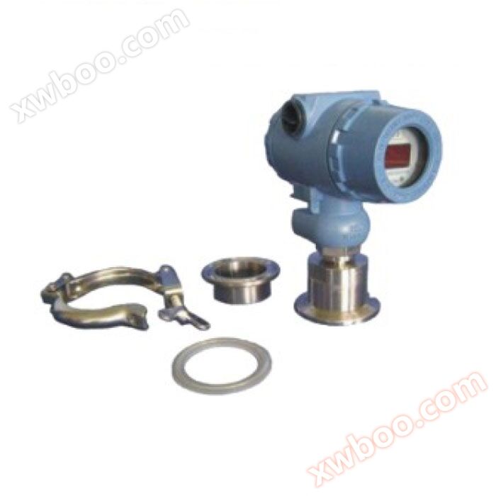
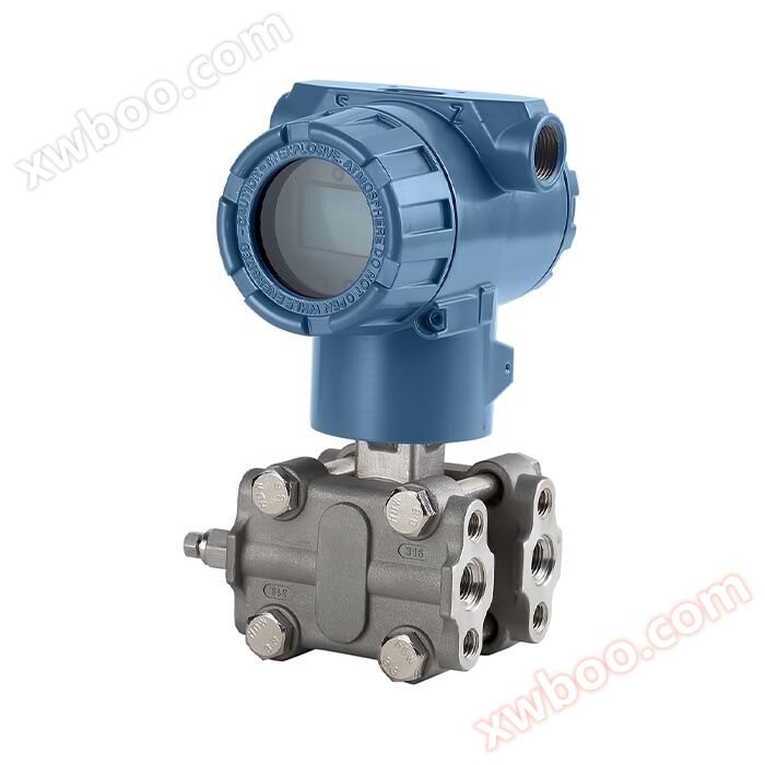
TK-3051DP Series - Differential Pressure Transmitter
NegotiableUpdate on 08/27
- Model
- Nature of the Manufacturer
- Producers
- Product Category
- Place of Origin
Overview
TK-3051DP Series - Differential Pressure Transmitter Material Measurement Diaphragm Box: Stainless Steel 316L Diaphragm: Stainless Steel 316L, Hastelloy C Process Flange: Stainless Steel 304 Nut and Bolt: Stainless Steel (A4) Filling Liquid: Silicone Oil Sealing Ring: Nitrile Rubber (NBR), Fluororubber (FKM), Polytetrafluoroethylene (PTFE) Transmitter Shell: Aluminum Alloy Material, Surface Spray Epoxy Resin Shell Sealing Ring: Nitrile Rubber (NBR) Nameplate: Stainless Steel 304 Weight: 3.5kg( None: LCD display, mounting bracket, process connection) .....
Product Details
TK-3051DP series differential pressure transmitter is used to measure the liquid level, density, pressure, and flow rate of liquids, gases, or vapors, and then convert them into 4-20mADC HART current signal output. It can also communicate with HART375 or HART475 handheld controllers for parameter setting, process monitoring, etc.
standard specifications
(Calibration range based on standard zero point, stainless steel 316L diaphragm, filled with silicone oil)
1: Performance specifications
Reference accuracy for range adjustment(including linearity, hysteresis, and repeatability starting from zero)± 0.075%
If TF>10 (TF=maximum range/adjustable range), it is:±(0.0075×TF)%
The square root output accuracy is 1.5 times the linear reference accuracy mentioned aboveOptional maximum precision of 0.05%.
Environmental temperature impact
|
Range code |
-Total impact from 20 ℃ to 70 ℃ |
|
A |
±(0.20×TF+0.10)%×Span |
|
B |
±(0.10×TF+0.10)%×Span |
|
C/D/E |
±(0.075×TF+0.10)%×Span |
|
Range code |
-Total impact of 40 ℃~-20 ℃ and 70 ℃~85 ℃ |
|
A |
±(0.20×TF+0.10)%×Span |
|
B |
±(0.10×TF+0.10)%×Span |
|
C/D/E/F |
±(0.075×TF+0.10)%×Span |
Static pressure effect
|
Range code |
influence quantity |
|
A |
±(0.15%URL+0.10%Span)/4MPa |
|
B |
±(0.10%URL+0.075%Span)/16MPa |
|
C/D/E/F |
±(0.05%URL+0.05%Span)/16MPa |
Overvoltage impact
|
Range code |
influence quantity |
|
A |
±0.2%×Span/4MPa |
|
B |
±0.2%×Span/16MPa |
|
C/D/E |
±0.1%×Span/16MPa |
long-term stability
|
Range code |
influence quantity |
|
A |
± 0.2% × Span/1 year |
|
B |
± 0.2% × Span/1 year |
|
C/D/E/F |
± 0.1% × Span/1 year |
Power supply impact:± 0.001%/10V (12-42V DC), negligible.
2: Functional specifications
Range and Range
|
Range/Range |
KPa |
mbar |
|
|
A |
range |
0.2~1 |
2~10 |
|
scope |
-1~1 |
-10~10 |
|
|
B |
range |
0.2~6 |
2~60 |
|
scope |
-6~6 |
-60~60 |
|
|
C |
range |
0.4~40 |
4~400 |
|
scope |
-40~40 |
-400~400 |
|
|
D |
range |
2.5~250 |
25~2500 |
|
scope |
-250~250 |
-2500~2500 |
|
|
E |
range |
10~1000 |
0.1~10 bar |
|
scope |
-500~1000 |
-5~10bar |
|
|
F |
range |
30~3000 |
0.3~30 bar |
|
scope |
-500~3000 |
-5~30bar |
|
Range limit
Within the upper and lower limits of the measuring range, it can be adjusted arbitrarily
Suggest selecting range codes with the lowest possible range ratio to optimize performance characteristics.
Zero point setting
The zero point and range can be adjusted to any value within the measurement range in the table, as long as the calibration range is ≥ the minimum range
Installation location impact
Changes in the installation position parallel to the membrane surface will not cause zero drift effects. If the installation position changes by more than 90 degrees from the membrane surface, there will be zero position effects within the range of<0.4KPa, which can be corrected by adjusting the zero position. No range influence.
output
2-wire system, 4-20mADC, optional HART output digital communication, optional linear or square root output.
Output signal limit: Imin=3.8mA, Imax=20.8mA
alarm current
Low alarm mode (minimum): 3.8 mA
High alarm mode (maximum): 20.8 mA
Non reporting mode (hold): Maintain the effective current value before the fault
Alarm current standard setting: high alarm mode
response time
The damping constant of the amplifier component is 0.1s; the time constant of the sensor is 0.1-1.6s, depending on the range and range ratio. The additional adjustable time constant is 0.1 to 60 seconds.
The impact on nonlinear outputs (such as square root function) depends on the function and can be calculated accordingly.
Preheating time:< 15s
ambient temperature
-40~85℃
-20~70 ℃ with LCD display and fluororubber sealing ring
Storage temperature/transportation temperature
-50~85℃; When equipped with LCD display: -40~85 ℃
work pressure
The rated working pressure is divided into three levels: 16MPa, 25MPa, and 40MPa
Static pressure limit
From an absolute pressure of 3.5KPa to the rated pressure, the protective pressure can be greater than 1.5 times the rated pressure and applied to both sides of the transmitter.
Unidirectional overload limit:Unidirectional overload can reach rated pressure
Electromagnetic Compatibility (EMC)
Refer to the "Electromagnetic Compatibility Appendix" on the next page
3: Installation
Power supply and load conditions
The power supply voltage is 24V, R ≤ (Us-12V)/Imax k Ω
Where Imax=20.8 mA
Maximum power supply voltage: 42VDC
Minimum power supply voltage: 12VDC, 15VDC (backlit LCD display)
Digital communication load range: 250-600 Ω
electrical connection
M20X1.5 cable sealing buckle, the terminal block is suitable for wires of 0.5-2.5mm2.
process connection
The two ends of the process connection flange have NPT 1/4 and UNF 7/16 internal threads.
4: Physical specifications
material
Measurement membrane box: stainless steel 316L
Diaphragm: Stainless steel 316L, Hastelloy C
Process flange: Stainless steel 304
Nut and bolt: stainless steel (A4)
Filling fluid: Silicone oil
Sealing rings: Nitrile rubber (NBR), Fluororubber (FKM)Polytetrafluoroethylene (PTFE)
Transmitter housing: made of aluminum alloy material, coated with epoxy resin on the outside
Shell sealing ring: Nitrile rubber (NBR)
Nameplate: Stainless Steel 304
Weight: 3.5kg (none: LCD display, mounting bracket, process connection)
degrees of protection provided by enclosure:IP67
Electromagnetic Compatibility Appendix
|
serial number |
test project |
Basic standards |
test conditions |
performance level |
|
1 |
Radiation interference (shell) |
GB/T 9254-2008 Table 5 |
30MHz~1000MHz |
qualified |
|
2 |
Conducted interference (DC power port) |
Table 1 of GB/T 9254-2008 |
0.15MHz~30MHz |
qualified |
|
3 |
Electrostatic discharge (ESD) immunity |
GB/T 17626.2-2006 |
4kV (contact) |
B |
|
4 |
Radio frequency electromagnetic field immunity |
GB/T 17626.3-2006 |
10V/m (80MHz~1GHz) |
A |
|
5 |
Power frequency magnetic field immunity |
GB/T 17626.8-2006 |
30A/m |
A |
|
6 |
Electrical fast transient burst immunity |
GB/T 17626.4-2008 |
2kV(5/50ns,5kHz) |
B |
|
7 |
Surge immunity |
GB/T 17626.5-2008 |
1kV (between lines) |
B |
|
8 |
Immunity to Conducted Interference Induced by Radio Frequency Field |
GB/T 17626.6-2008 |
3V(150KHz~80MHz) |
A |
Note: (1) A Performance Level Description: During testing, the performance is normal within the technical specification limits.
(2) B Performance Level Description: During testing, the functionality or performance may temporarily decrease or be lost, but it can recover on its own without changing the actual operating conditions, storage, and data.
External dimensions
Horizontal piping connection method (side) Horizontal piping connection method (front)

Wall mounted connection method, vertical piping connection method

5: Electrical connection diagram

6: Process Connection Instructions

7: CHD810 series intelligent differential pressure transmitter model and specification code
|
CHD810-DP |
CHD810-DP Intelligent Differential Pressure Transmitter |
|
Code 1 |
measurement range |
|
B |
0.2~6 KPa |
|
C |
1.0~40KPa |
|
D |
2.5~250KPa |
|
E |
10~1000KPa |
|
F |
30~3000KPa |
|
Code 2 |
output |
|
E |
Standard intelligent (4~20) mA DC two-wire system+HART protocol digital communication |
|
J |
Standard intelligent (4~20) mA DC two-wire system+HART protocol digital communication+square root signal output |
|
Code 3 |
Isolation Diaphragm |
|
22 |
316L stainless steel |
|
23 |
Hastelloy C |
|
24 |
Monel |
|
25 |
Tantalum |
|
Code 4 |
Fill liquid |
|
D |
silicone oil |
|
F |
Fluoro oil |
|
Code 5 |
electrical interface |
|
M |
M20 × 1.5 internal thread |
|
N |
1/2NPT internal thread |
|
Code 6 |
Location of relief valve |
|
A |
No relief valve (with plug added) |
|
B |
Process flange side upper part |
|
C |
Process flange side lower part |
|
Code 7 |
mounting bracket |
|
N |
No installation bracket |
|
B1 |
Pipe bending bracket (carbon steel) |
|
B2 |
Plate mounted bending bracket (carbon steel) |
|
B3 |
Pipe mounted flat bracket (carbon steel) |
|
B5 |
Pipe bending bracket (stainless steel) |
|
B6 |
Plate mounted bending bracket (stainless steel) |
|
B7 |
Pipe mounted flat bracket (stainless steel) |
|
Code 8 |
static pressure |
|
A |
10MPa |
|
B |
16Mpa |
|
C |
25MPa |
|
Code 9 |
Explosion-proof rating |
|
N |
Ordinary type (without explosion-proof) |
|
D |
Explosion proof Exd Ⅱ CT6 |
|
I |
Intrinsic safety explosion-proof Exia Ⅱ CT6 |
|
Code 10 |
accuracy class |
|
2 |
Level 0.2 |
|
5 |
Level 0.5 |
|
7 |
0.075 level |
|
6 |
0.065 level |
|
8 |
0.05 level |
|
option code |
option |
|
N |
With "waist" shaped connector: NPT1/2 cone tube internal thread |
|
J |
With "T-shaped" joint: M20 × 1.5 external thread and rear welded pressure pipe (stainless steel) |
|
F |
Equipped with a "waist" shaped joint and NPT1/2 pressure crossing head and rear welded pressure pipe (stainless steel) |
|
P |
No process connection (l/4 NPT internal thread on the chamber flange) |
|
K |
Degreasing and cleaning treatment |
|
L |
Hanging license plate |
|
H |
Lightning protection (withstand transient voltage) |
|
E |
English nameplate |
|
V3 |
triple valve manifold |
|
V5 |
Five valve group |
|
M5 |
LCD display |
|
N |
No header |
|
CHD810-DR |
CHD810-DR Intelligent Micro Differential Pressure Transmitter |
|
Code 1 |
measurement range |
|
A |
0.2~1KPa |
|
B |
0.6~6KPa |
|
Code 2 |
output |
|
E |
Standard intelligent (4~20) mA DC two-wire system+HART protocol digital communication |
|
J |
Standard intelligent (4~20) mA DC two-wire system+HART protocol digital communication+square root signal output |
|
Code 3 |
Isolation Diaphragm |
|
22 |
316L stainless steel |
|
23 |
Hastelloy C |
|
24 |
Monel |
|
25 |
Tantalum |
|
Code 4 |
Fill liquid |
|
D |
silicone oil |
|
F |
Fluoro oil |
|
Code 5 |
electrical interface |
|
M |
M20 × 1.5 internal thread |
|
N |
1/2NPT internal thread |
|
Code 6 |
Location of relief valve |
|
A |
No relief valve (with plug added) |
|
B |
Process flange side upper part |
|
C |
Process flange side lower part |
|
Code 7 |
mounting bracket |
|
N |
No installation bracket |
|
B1 |
Pipe bending bracket (carbon steel) |
|
B2 |
Plate mounted bending bracket (carbon steel) |
|
B3 |
Pipe mounted flat bracket (carbon steel) |
|
B5 |
Pipe bending bracket (stainless steel) |
|
B6 |
Plate mounted bending bracket (stainless steel) |
|
B7 |
Pipe mounted flat bracket (stainless steel) |
|
Code 8 |
static pressure |
|
A |
200KPa |
|
B |
4Mpa |
|
Code 9 |
Explosion-proof rating |
|
N |
Ordinary type (without explosion-proof) |
|
D |
Explosion proof Exd Ⅱ CT6 |
|
I |
Intrinsic safety explosion-proof Exia Ⅱ CT6 |
|
Code 10 |
accuracy class |
|
2 |
Level 0.2 |
|
5 |
Level 0.5 |
|
1 |
0.1 level |
|
7 |
0.075 level |
|
option code |
option |
|
N |
With "waist" shaped connector: NPT1/2 cone tube internal thread |
|
J |
With "T-shaped" joint: M20 × 1.5 external thread and rear welded pressure pipe (stainless steel) |
|
F |
Equipped with a "waist" shaped joint and NPT1/2 pressure crossing head and rear welded pressure pipe (stainless steel) |
|
P |
No process connection (l/4 NPT internal thread on the chamber flange) |
|
K |
Degreasing and cleaning treatment |
|
L |
Hanging license plate |
|
H |
Lightning protection (withstand transient voltage) |
|
E |
English nameplate |
|
V3 |
triple valve manifold |
|
V5 |
Five valve group |
|
M5 |
LCD display |
|
M3 |
No header |
|
CHD810-GP |
CHD810-GP Intelligent Pressure Transmitter |
|
|
Code 1 |
measurement range |
|
|
B |
0.2~6 KPa |
|
|
C |
1.0~40KPa |
|
|
D |
2.5~250KPa |
|
|
E |
10~1000KPa |
|
|
F |
30~3000KPa |
|
|
Code 2 |
output |
|
|
E |
Standard intelligent (4~20) mA DC two-wire system+HART protocol digital communication |
|
|
J |
Standard intelligent (4~20) mA DC two-wire system+HART protocol digital communication+square root signal output |
|
|
Code 3 |
Isolation Diaphragm |
|
|
22 |
316L stainless steel |
|
|
23 |
Hastelloy C |
|
|
24 |
Monel |
|
|
25 |
Tantalum |
|
|
Code 4 |
Fill liquid |
|
|
D |
silicone oil |
|
|
F |
Fluoro oil |
|
|
Code 5 |
electrical interface |
|
|
M |
M20 × 1.5 internal thread |
|
|
N |
1/2NPT internal thread |
|
|
Code 6 |
Location of relief valve |
|
|
A |
No relief valve (with plug added) |
|
|
B |
Process flange side upper part |
|
|
C |
Process flange side lower part |
|
|
Code 7 |
mounting bracket |
|
|
N |
No installation bracket |
|
|
B1 |
Pipe bending bracket (carbon steel) |
|
|
B2 |
Plate mounted bending bracket (carbon steel) |
|
|
B3 |
Pipe mounted flat bracket (carbon steel) |
|
|
B5 |
Pipe bending bracket (stainless steel) |
|
|
B6 |
Plate mounted bending bracket (stainless steel) |
|
|
B7 |
Pipe mounted flat bracket (stainless steel) |
|
|
Code 8 |
Explosion-proof rating |
|
|
N |
Ordinary type (without explosion-proof) |
|
|
D |
Explosion proof Exd Ⅱ CT6 |
|
|
I |
Intrinsic safety explosion-proof Exia Ⅱ CT6 |
|
|
Code 9 |
accuracy class |
|
|
2 |
Level 0.2 |
|
|
5 |
Level 0.5 |
|
|
7 |
0.075 level |
|
|
6 |
0.065 level |
|
|
8 |
0.05 level |
|
|
option code |
option |
|
|
N |
With "waist" shaped connector: NPT1/2 cone tube internal thread |
|
|
J |
With "T-shaped" joint: M20 × 1.5 external thread and rear welded pressure pipe (stainless steel) |
|
|
F |
Equipped with a "waist" shaped joint and NPT1/2 pressure crossing head and rear welded pressure pipe (stainless steel) |
|
|
P |
No process connection (l/4 NPT internal thread on the chamber flange) |
|
|
K |
Degreasing treatment |
|
|
L |
Hanging license plate |
|
|
H |
Lightning protection (withstand transient voltage) |
|
|
E |
English nameplate |
|
|
M5 |
LCD display |
|
|
N |
No header |
|
|
CHD810-AP |
CHD810-AP Intelligent Absolute Pressure Transmitter |
|
Code 1 |
measurement range |
|
B |
0.2~6 KPa |
|
C |
1.0~40KPa |
|
D |
2.5~250KPa |
|
E |
10~1000KPa |
|
Code 2 |
output |
|
E |
Standard intelligent (4~20) mA DC two-wire system+HART protocol digital communication |
|
J |
Standard intelligent (4~20) mA DC two-wire system+HART protocol digital communication+square root signal output |
|
Code 3 |
Isolation Diaphragm |
|
22 |
316L stainless steel |
|
23 |
Hastelloy C |
|
24 |
Monel |
|
25 |
Tantalum |
|
Code 4 |
Fill liquid |
|
D |
silicone oil |
|
F |
Fluoro oil |
|
Code 5 |
electrical interface |
|
M |
M20 × 1.5 internal thread |
|
N |
1/2NPT internal thread |
|
Code 6 |
Location of relief valve |
|
A |
No relief valve (with plug added) |
|
B |
Process flange side upper part |
|
C |
Process flange side lower part |
|
Code 7 |
mounting bracket |
|
N |
No installation bracket |
|
B1 |
Pipe bending bracket (carbon steel) |
|
B2 |
Plate mounted bending bracket (carbon steel) |
|
B3 |
Pipe mounted flat bracket (carbon steel) |
|
B5 |
Pipe bending bracket (stainless steel) |
|
B6 |
Plate mounted bending bracket (stainless steel) |
|
B7 |
Pipe mounted flat bracket (stainless steel) |
|
Code 8 |
Explosion-proof rating |
|
N |
Ordinary type (without explosion-proof) |
|
D |
Explosion proof Exd Ⅱ CT6 |
|
I |
Intrinsic safety explosion-proof Exia Ⅱ CT6 |
|
Code 9 |
accuracy class |
|
2 |
Level 0.2 |
|
5 |
Level 0.5 |
|
7 |
0.075 level |
|
6 |
0.065 level |
|
8 |
0.05 level |
|
option code |
option |
|
N |
With "waist" shaped connector: NPT1/2 cone tube internal thread |
|
J |
With "T-shaped" joint: M20 × 1.5 external thread and rear welded pressure pipe (stainless steel) |
|
F |
Equipped with a "waist" shaped joint and NPT1/2 pressure crossing head and rear welded pressure pipe (stainless steel) |
|
P |
No process connection (l/4 NPT internal thread on chamber flange) |
|
K |
Degreasing treatment |
|
L |
Hanging license plate |
|
H |
Lightning protection (withstand transient voltage) |
|
E |
English nameplate |
|
M5 |
LCD display |
|
N |
No header |