-
E-mail
tkyb2005@126.com
-
Phone
18072820595
-
Address
No. 536 Shunfeng Road, Qianjiang Economic Development Zone, Yuhang District, Hangzhou City
Product Categories
Hangzhou Tiankang Instrument Co., Ltd

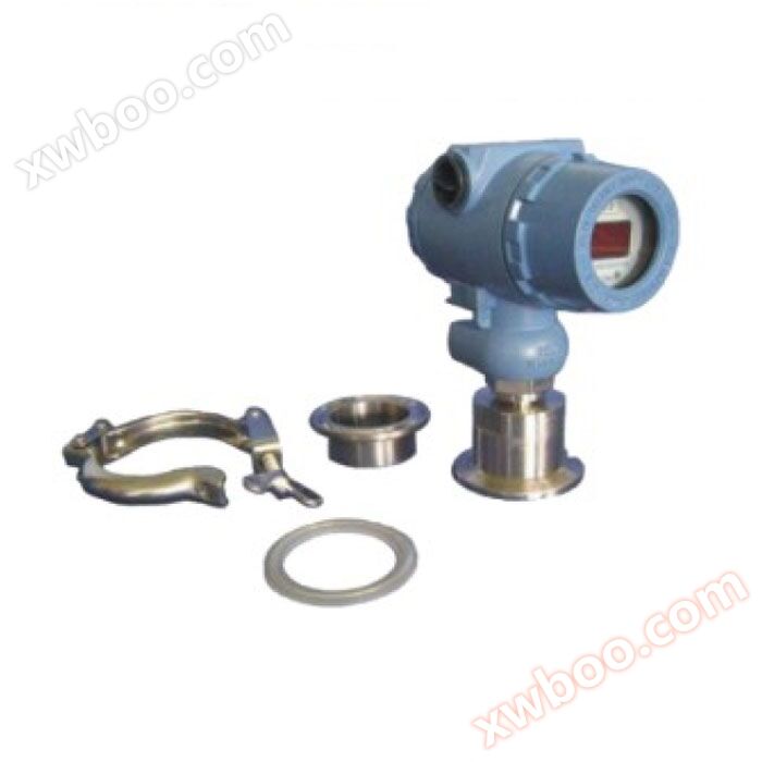
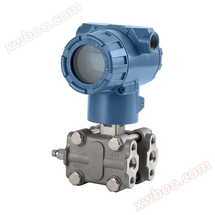
TK-3051DP flange installation transmitter
NegotiableUpdate on 10/27
- Model
- Nature of the Manufacturer
- Producers
- Product Category
- Place of Origin
Overview
TK-3051DP flange installation transmitter material measurement diaphragm box: stainless steel 316L diaphragm: stainless steel 316L, Hastelloy C, tantalum diaphragm FEP, PFA, PTFE coating process flange: stainless steel 304 filling fluid: silicone oil, vegetable oil sealing ring: nitrile rubber (NBR), fluororubber (FKM), polytetrafluoroethylene (PTFE) transmitter housing: aluminum alloy material, coated with epoxy resin outer shell sealing ring: nitrile rubber (NBR) nameplate: stainless steel 304 .....
Product Details
1: Application
The diaphragm box of the flange mounted transmitter is used to prevent the medium in the pipeline from directly entering the pressure sensor component of the differential pressure transmitter. It uses filling liquid such as silicone oil to transmit pressure between it and the transmitter.
The CHD830-LT liquid level transmitter is used to measure the liquid level, density, pressure, and flow rate of liquids, gases, or vapors, and then convert them into 4-20mADC HART current signals for output. It can also communicate with HART375 or HART475 handheld controllers for parameter setting, process monitoring, etc. The measurement range of CHD830-LT series liquid level transmitter (before relocation) is 0-1kPa to 3000KPa, and the rated pressure of the liquid level flange is 1.6/4MPa, 6.4MPa, 10MPa, 150psi, 300psi or 600psi, respectively.
2: Working principle and structure
The CHD830-LT flange mounted transmitter structure consists of a CHD830 series differential pressure transmitter and a welded liquid level flange. Its working principle is the same as that of the CHD810 series differential pressure transmitter (see CHD810 series differential pressure transmitter technical specification), except that the pressure transmission path on the positive pressure side is slightly different: the pressure acting on the high pressure side first passes through the diaphragm and filling liquid on the liquid level flange, then through the transmitter body, and finally reaches the high pressure side of the measuring sensor.
3: Input
Measurement parameters: differential pressure, liquid level
measurement range
Lower limit value: Starting from -100% URL (continuously adjustable)
Lower limit value: up to+100% URL (continuously adjustable)
range
Table 1 Comparison Table of Range Code and Range Range Relationship
|
Range code |
Minimum range |
maximum range |
Rated pressure (maximum value) |
|
B |
1kPa |
40kPa |
Rated pressure of liquid level flange |
|
C |
2.5kPa |
250kPa |
|
|
D |
10kPa |
1000kPa |
|
|
E |
30Kpa |
3000KPa |
Table 2 Comparison Table of Level Flange and Minimum Range Relationship
|
Liquid level flange |
Nominal diameter |
Minimum range |
|
Flat flange type |
DN 50/2” |
10kPa |
|
DN 80/3” |
1kPa |
|
|
DN 4” |
1kPa |
|
|
Insert Simplified Form |
DN 50/2” |
16kPa |
|
DN 80/2” |
1kPa |
|
|
DN 4” |
1kPa |
The minimum range for flange mounted transmitters should be the larger of the minimum ranges in Table 1 and Table 2. The range of adjustment shall not be less than the minimum range. The maximum range of the liquid level transmitter should be the minimum value between the maximum range of the transmitter body and the rated pressure of the liquid level flange.
4: Output
output signal
2-wire system, 4-20mADC HART output, digital communication, HART protocol loaded on 4-20mADC signal.
Output signal limit: Imin=3.8mA, Imax=20.8mA
Alarm current (mode can be set)
Low alarm mode (minimum): 3.8mA
High alarm mode (maximum): 20.8 mA
Non reporting mode (hold): Maintain the effective current value before the fault
Alarm current standard setting: high alarm mode
5: Response time
The damping constant of the amplifier component is 0.1s; the time constant of the sensor and liquid level flange is 0.2-2s, depending on the range and range ratio. The additional adjustable time constant is 0.1 to 60 seconds.
6: General conditions
6.1 Installation conditions
The liquid level flange transmitter can be directly fixed in any position. The optimal state is to keep the process flange axis in a vertical position, and any positional deviation will result in a correctable zero offset. The electronic case can rotate up to 360 °, and the positioning screw can fix it in any position.
6.2 Environmental conditions
ambient temperature
Minimum: depends on the filling fluid
最高:85℃
-20~70 ℃ with LCD display and fluororubber sealing ring
Storage temperature/transportation temperature
Minimum: depends on the filling fluid
最高:85℃
relative humidity
0~100%
impact-resistant
Acceleration: 50g
Duration: 11ms
shockproof
2g to 500Hz
Electromagnetic Compatibility (EMC)
See Table 3 "Electromagnetic Compatibility Appendix" on the next page
6.3 Limit of process medium
Temperature limit of medium: -40~180 ℃
Pressure limit of transmitter body
From an absolute pressure of 3.5kPa to the rated pressure, the protective pressure can be greater than 1.5 times the rated pressure and applied to both sides of the transmitter.
Rated pressure of liquid level flange
ANSI standard: 150psi to 600psi
DIN standard: PN 1.6MPa to PN 10MPa
Unidirectional overload limit
The low-pressure side is the rated pressure of the transmitter body, and the high-pressure side is the rated pressure of the liquid level flange, which may result in correctable zero drift.
Weight:DN 50/2 "weighs approximately 7-10kg; DN 80/3" weighs approximately 8-11kg; DN 4 "weighs approximately 9-12kg.
explosion-proof performance
NEPSI Explosion proof Permit: Ex d Ⅱ C T6
NEPSI intrinsic safety license: Ex ia Ⅱ C T6
Allowable operating temperature range: -40 ℃ to 70 ℃
6.4 Power Supply and Load Conditions
The power supply voltage is 24V
R≤(Us-12V)/Imax kΩ
Where Imax=20.8 mA
Maximum power supply voltage: 42VDC
Minimum power supply voltage: 12VDC, 15VDC (backlit LCD display)
Digital communication load range: 230-600 Ω
material
Measurement membrane box: stainless steel 316L
Membrane: Stainless steel 316L, Hastelloy C, Tantalum membrane, FEP, PFA, PTFE membrane
Process flange: Stainless steel 304
Filling fluid: silicone oil, vegetable oil
Sealing rings: Nitrile rubber (NBR), Fluororubber (FKM)Polytetrafluoroethylene (PTFE)
Transmitter housing: made of aluminum alloy material, coated with epoxy resin on the outside
Shell sealing ring: Nitrile rubber (NBR)
Nameplate: Stainless Steel 304
electrical connection
M20X1.5 cable sealing buckle, the terminal block is suitable for wires of 0.5-2.5mm2.
process connection
The low voltage side of the transmitter has an internal thread of UNF 7/16. The liquid level flange on the high-pressure side of the transmitter complies with ANSI or DIN standards. Can be installed directly, please refer to the dimension diagram.
Shell protection levelIP67
Table 3 Electromagnetic Compatibility Appendix
|
serial number |
test project |
Basic standards |
test conditions |
performance level |
|
1 |
Radiation interference (shell) |
GB/T 9254-2008 Table 5 |
30MHz~1000MHz |
qualified |
|
2 |
Conducted interference (DC power port) |
Table 1 of GB/T 9254-2008 |
0.15MHz~30MHz |
qualified |
|
3 |
Electrostatic discharge (ESD) immunity |
GB/T 17626.2-2006 |
4kV (contact) |
B |
|
4 |
Radio frequency electromagnetic field immunity |
GB/T 17626.3-2006 |
10V/m (80MHz~1GHz) |
A |
|
5 |
Power frequency magnetic field immunity |
GB/T 17626.8-2006 |
30A/m |
A |
|
6 |
Electrical fast transient burst immunity |
GB/T 17626.4-2008 |
2kV(5/50ns,5kHz) |
B |
|
7 |
Surge immunity |
GB/T 17626.5-2008 |
1kV (between lines) |
B |
|
8 |
Immunity to Conducted Interference Induced by Radio Frequency Field |
GB/T 17626.6-2008 |
3V(150KHz~80MHz) |
A |
Note: (1) A Performance Level Description: During testing, the performance is normal within the technical specification limits.
(2) B Performance Level Description: During testing, the functionality or performance may temporarily decrease or be lost, but it can recover on its own without changing the actual operating conditions, storage, and data.
Overall dimensions

4. Dimensional Table of Liquid Level Flange Structure
|
Nominal diameter |
rated pressure |
ΦD |
ΦK |
Φd1 |
Φd2 |
Φd3 |
t |
b |
Require bolts |
|
|
plug-in |
flat |
quantity |
thread |
|||||||
|
DN 50 |
PN1.6/4MPa |
165 |
125 |
48.3 |
57 |
102 |
3+0.5 |
20 |
4 |
M16 |
|
(Sealing surface DIN2526E type) |
PN 6.4MPa |
18 |
135 |
48.3 |
57 |
102 |
3+0.5 |
26 |
4 |
M20 |
|
(Flange DIN2501) |
PN 10MPa |
195 |
145 |
48.3 |
57 |
102 |
3+0.5 |
28 |
4 |
M20 |
|
DN 80 |
PN1.6/4MPa |
200 |
160 |
76 |
75 |
138 |
3+0.5 |
24 |
8 |
M16 |
|
(Sealing surface DIN2526E type) |
PN 6.4MPa |
215 |
170 |
76 |
75 |
138 |
3+0.5 |
28 |
8 |
M20 |
|
(Flange DIN2501) |
PN 10MPa |
230 |
180 |
76 |
75 |
138 |
3+0.5 |
32 |
8 |
M24 |
|
DN 2' |
150psi |
152.4 |
120.6 |
48.3 |
57 |
92.1 |
3+0.5 |
17.4 |
4 |
M18 |
|
300psi |
165.1 |
127.0 |
48.3 |
57 |
92.1 |
3+0.5 |
20.6 |
8 |
M18 |
|
|
600psi |
165.1 |
127.0 |
48.3 |
57 |
92.1 |
6.35 |
31.75 |
8 |
M18 |
|
|
DN 3' |
150psi |
190.5 |
152.4 |
76 |
75 |
127 |
3+0.5 |
22.2 |
4 |
M16 |
|
300psi |
209.5 |
168.3 |
76 |
75 |
127 |
3+0.5 |
27.0 |
8 |
M20 |
|
|
600psi |
209.5 |
168.3 |
76 |
75 |
127 |
6.35 |
38.05 |
8 |
M20 |
|
|
DN 4“ |
150psi |
229 |
191 |
89 |
89 |
157 |
3+0.5 |
30 |
8 |
M18 |
|
(ANSI B 16.5 RF type) |
300psi |
255 |
200 |
89 |
89 |
157 |
3+0.5 |
32 |
8 |
M18 |
Note: Users can choose to install bolts and nuts.
7: Electrical connection diagram

8: Instructions for Low Voltage End Process Connection

|
CHD830-LT |
CHD830-LT flange mounted transmitter |
|
|
Code 1 |
measurement range |
|
|
B |
1.0~40Kpa |
|
|
C |
2.5~250Kpa |
|
|
D |
10~1000Kpa |
|
|
E |
30~3000KPa |
|
|
Code 2 |
output |
|
|
E |
Standard intelligent (4~20) mA DC two-wire system+HART protocol digital communication |
|
|
J |
Standard intelligent (4~20) mA DC two-wire system+HART protocol digital communication+square root signal output |
|
|
Code 3 |
Flange Standard |
|
|
D |
HG/T20592-2009 (DIN) |
|
|
A |
HG/T20615-2009 (ANSI) |
|
|
Code 4 |
Flange size (DIN) |
Flange size (ANSI) |
|
A |
DN25 |
1 inch |
|
B |
DN40 |
1.5 inches |
|
C |
DN50 |
2 inches |
|
D |
DN80 |
3 inches |
|
E |
DN100 |
4 inches |
|
T |
Special size |
|
|
Code 5 |
Flange grade (DIN) |
Flange Class (ANSI) |
|
A |
PN10 / PN16 |
Level 150 |
|
B |
PN25 / PN40 |
Level 300 |
|
C |
PN2.5 / PN6 |
|
|
T |
Special size |
|
|
Code 6 |
Insertion tube type |
|
|
0 |
Flat flange type |
|
|
1 |
50mm |
|
|
2 |
100mm |
|
|
3 |
150mm |
|
|
T |
Special size |
|
|
Code 7 |
Membrane material |
|
|
A |
316 stainless steel |
|
|
B |
Hastelloy C |
|
|
C |
Tantalum |
|
|
F |
F46 film coating |
|
|
P |
PFA coating |
|
|
Code 8 |
Fill liquid |
temperature limit |
|
D |
Ordinary silicone oil DC200 |
-45 to 205 ℃ |
|
C |
High temperature silicone oil DC704 |
0 to 315 ℃ |
|
F |
fluorinated oil |
-18 to 204 ℃ |
|
Code 9 |
electrical interface |
|
|
M |
M20 × 1.5 internal thread |
|
|
N |
1/2NPT internal thread |
|
|
Code 10 |
Explosion-proof rating |
|
|
N |
Ordinary type (without explosion-proof) |
|
|
D |
Explosion proof Exd Ⅱ CT6 |
|
|
I |
Intrinsic safety explosion-proof Exia Ⅱ CT6 |
|
|
Code 11 |
accuracy class |
|
|
2 |
Level 0.2 |
|
|
5 |
Level 0.5 |
|
|
7 |
0.075 level |
|
|
1 |
0.1 level |
|
|
Option code |
option |
|
|
A |
F46 film coating |
|
|
B |
PFA coating |
|
|
C |
Stainless steel flushing connection ring chamber |
|
|
K |
Degreasing treatment |
|
|
L |
Hanging license plate |
|
|
H |
Lightning protection (withstand transient voltage) |
|
|
E |
English nameplate |
|
|
M5 |
LCD display |
|
|
N |
No header |
|