-
E-mail
25291658@qq.com
-
Phone
13951262528
-
Address
No. 258-8 Huancheng West Road, Jinhu County Economic Development Zone, Huai'an City, Jiangsu Province
Product Categories
Dexon Instruments (Huai'an) Co., Ltd
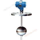
DKS-UQZ-Y53 series float level transmitter
NegotiableUpdate on 09/18
- Model
- Nature of the Manufacturer
- Producers
- Product Category
- Place of Origin
Overview
Suitable for liquid level measurement in underground storage tanks. This series of float level transmitters can be displayed locally or connected to secondary display instruments.
Product Details
-
summary:DKS-UQZ-Y53 型系列浮球液位变送器Suitable for water treatment in industries such as refining, chemical, papermaking, food, and pharmaceuticals, as well as for measuring the liquid level position of media in various high-level and low-level containers in industrial production. Especially suitable for liquid level measurement in underground storage tanks. This series of float level transmitters can be displayed locally or connected to secondary display instruments.DKS-UQZ-Y53 型系列浮球液位变送器It consists of magnetic floating ball, measuring conduit, measuring element, circuit unit, junction box housing, and installation components. The float changes synchronously with the liquid level, so that the resistance inside the sensor changes linearly. Then, the converter converts the resistance change into a current amplified to 4-20mA two-wire standard signal output for remote detection and control of the measured liquid level. It is convenient to adjust the zero point and upper and lower limit alarm points within the full range.
-
Measurement range: L: within 0-6000mm, users can choose freely
(PVC 材质 L:0~ 3000mm)
Output signal: 4-20mADC two-wire standard signal
Accuracy: ± 10mm
Working pressure: ≤ 2.5MPa (can be designed separately for pressures above 2.5MPa)
防腐型≤0.6MPa
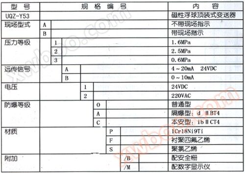
Model specification description
Other parameters:
介质粘度: ≤1.25St( 1 St=10-4m2/S )
ф 120, ф 76 floating balls, medium density: ≥ 0.55g/cm3
Float balls of ф 52 and ф 46, various liquids with medium density ≥ 0.8g/cm3.
Medium temperature: -40 to+135 ℃
Environmental temperature: -40 to+60 ℃
Wetting material: 1Cr18Ni9Ti polytetrafluoroethylene polyvinyl chloride
Load impedance: 0-500 Ω (when powered by 24VDC)
供电电压: 24VDC
Outlet connector: M20 × 1.5 (internal)
Protection of junction box casing: IP65
Explosion proof form: intrinsic safety type: ib Ⅱ CT4
Explosion proof type: dIIBT4
Connection flange: The flange is JB/T8.2-94, DN150, PN0.6 1.6 2.5MPa. If other flange standards (such as GB, ANSI, HGJ, etc.) are used, please indicate when placing an order.
Float ball: Standard supply ф 120 guide rod is ф 22
Special supply: The guide rod for ф 76 is ф 20, while the guide rods for ф 46 and ф 52 are ф 12Instructions for use:
1. The installation position of the liquid level transmitter should be selected at the location where the liquid fluctuation is small, avoiding or far away from the inlet and outlet of the liquid medium, to reduce the impact of the medium fluid on the liquid level transmitter.
2. If the range of the liquid level transmitter exceeds 3 meters, it needs to be positioned at the bottom of the pipe.
3. The neck diameter of the flange connection between the liquid level transmitter and the container should be greater than 125mm, so that the ф 120mm float can be removed or inserted from the container during installation.
4. Remove the safety barrier and connect the wires at both ends of the safety barrier to form a regular or explosion-proof type. The specific installation requirements for safety barriers can be found in the product manual. When debugging this system, the safety barrier must be disconnected and the wires at both ends of the safety barrier must be directly connected to prevent the safety barrier from burning out.
Similar Product Recommend


