-
E-mail
2881392111@qq.com
-
Phone
13611962943
-
Address
No. 253 Yulu Road, Jiading District, Shanghai
Product Categories
Ankerui E-commerce (Shanghai) Co., Ltd


Intelligent power online monitoring device for low-voltage distribution system
NegotiableUpdate on 11/20
- Model
- Nature of the Manufacturer
- Producers
- Product Category
- Place of Origin
Overview
The intelligent online monitoring device for low-voltage distribution system can receive and process the leakage and temperature signals sent by various detectors in real time, and display them on the screen. When a leakage or overtemperature alarm occurs, the monitoring device can emit sound and light alarm signals, and display the fault location and alarm type on the screen ..
Product Details
Intelligent power online monitoring device for low-voltage distribution system
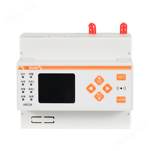
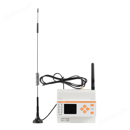
1. Overview
The ARCM600-Z smart power online monitoring device (hereinafter referred to as the monitoring device) is an intelligent power device designed for TT and TN systems below 0.4kV. It has functions such as three-phase AC measurement, leakage monitoring, temperature monitoring, four quadrant energy metering, remote signal input and output, as well as 4G communication. It monitors and manages fire hazard parameters such as residual current and wire temperature in the distribution circuit.
The monitoring device can receive and process the leakage and temperature signals sent by various detectors in real time, and display them on the screen. When a leakage or overtemperature alarm occurs, the monitoring device can emit sound and light alarm signals, display the fault location and alarm type on the screen, and have functions such as data storage, query, and alarm control signal output.
Intelligent power online monitoring device for low-voltage distribution systemReasonable structure, small size, high reliability, strong functionality, easy maintenance, high cost-effectiveness, intuitive and easy-to-use system interface.
2. Product model


3. Technical parameters

4. Installation and wiring
4.1. Appearance and installation dimensions (unit: mm)

4.2. Installation Requirements
① Installation environment: The monitoring device should be installed in a dry, clean, and away from heat sources and strong electromagnetic fields.
② Installation method: 35mm rail installation, wall mounted installation.
③ Installation location: Priority should be given to installing in the fire control room. If there is no fire control room, it can also be installed on the walls of a manned substation (distribution room) or a manned room.
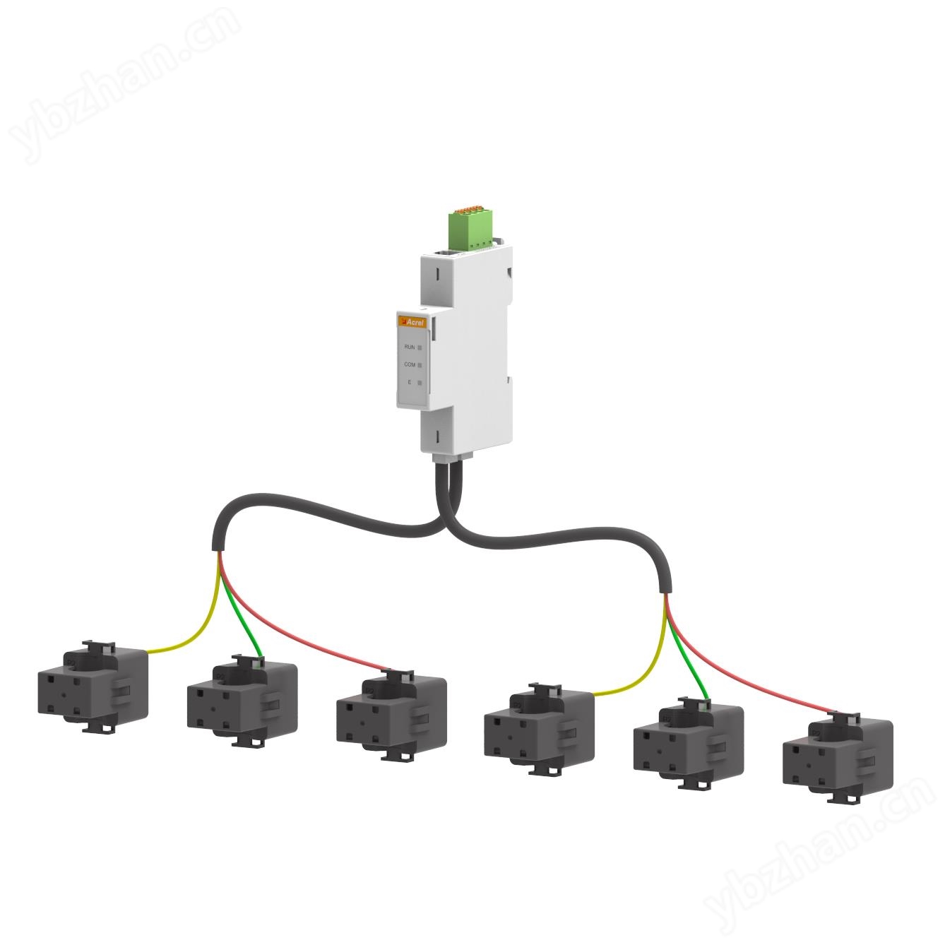
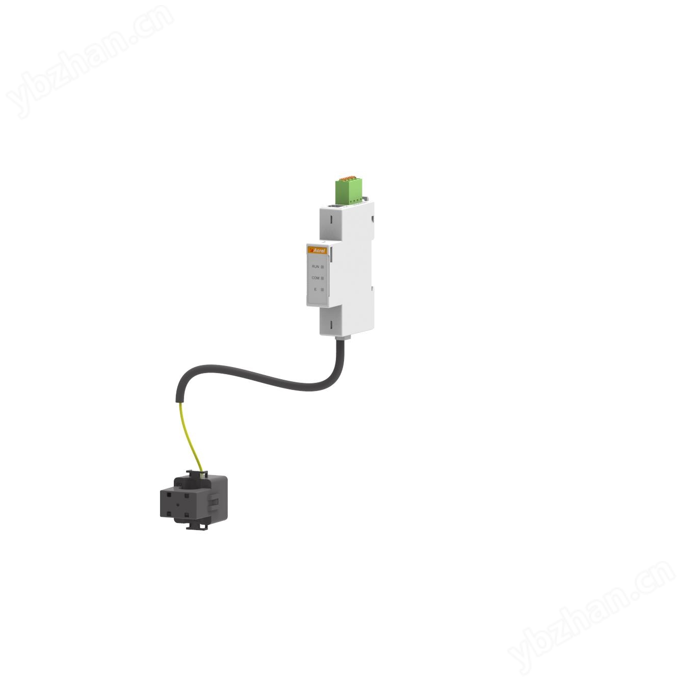
4.3. Wiring Instructions
Upper row terminals: "41, 42, 43, 44, 45, 46, 47, 48" are inputs for residual current signals and temperature signals; 21 and 22 "are communication 1; 19 and 20 represent communication 2; 15 and 16 represent two bus communication; 17 and 18 are pulse outputs; 24, 25, 28 "switch input;

Bottom row terminals: "12, 13" are power interfaces; 1, 2, 3, 4 "are voltage input signal terminals; 5, 6, 7, 8, 9, 10 "are current input signal terminals; Relay outputs of "34, 35".

Similar Product Recommend