-
E-mail
weilimail@126.com
-
Phone
13619810814
-
Address
No. 6, Beijiao Industrial Park, Kaifeng City, Henan Province
Product Categories
Kaifeng Weili Instrument Testing Co., Ltd
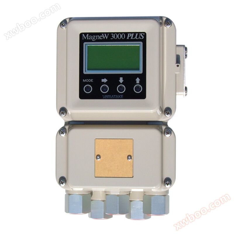
MGG Intelligent Electromagnetic Converter
NegotiableUpdate on 07/29
- Model
- Nature of the Manufacturer
- Producers
- Product Category
- Place of Origin
Overview
There are two types of electromagnetic flowmeter converters using new technology: ordinary type (MGG14C) and slurry type (MGH14C), which can not only be used for general process detection, but also for measuring slurry, pulp and paste liquids
Product Details
Product parameters
| Main power supply: | AC100V,110V,115V/120V±10% |
| AC200V,220V,230V/240V±10% | |
| DC24V±10% | |
| Frequency: | 50Hz or 60Hz |
| Power consumption: | ≤ 13W (slurry type ≤ 80W) |
| Display and buttons: | Three row LCD display with backlight, used for displaying percentage flow, instantaneous flow, and cumulative flow, with 4 infrared touch buttons for data settings. |
| Counter: | Positive cumulative flow, negative cumulative flow, and differential cumulative flow. |
| Input signal: | a. Flow signal: a voltage signal from the detector that is proportional to the flow rate. |
| b. Contact input (optional): Solid state contact or non voltage contact. | |
| output signal | a. Analog output: 4-20mADC (choose digital output) 1. No SFC communication: 0.8mA~22.4mA (-20%~+115%) Load resistance: 0-600 Ω 2. SFC communication available: 3.2mA~22.4mA (-5%~+115%) External power supply for SFC communication: DC16~45V (optional) 3. Load resistance (Ω)=(external power supply for communication -8.5V)/0.02 |
| b. Digital output: DE (choose analog output) | |
| c. Contact output (optional): Open collector, contact capacity 30VDC maximum, 200mA maximum (optional). 1. Alarm driven contact output: For self diagnosis, no-load detection, and alarm driven contact output for flow upper and lower limit values. 2. Output of range discrimination: The output of ID signal contacts for large, small, and forward/reverse direction ranges. 3. Pre set state output (pulse output type): When the built-in counter reaches the preset value, it outputs a signal to the next contact. 4. Self diagnostic alarm output: When the self diagnostic function detects an error, it outputs a signal to an alarm driving contact. 5. Empty load detection alarm output: When the fluid level in the detector is lower than the electrode level, it outputs a signal to an alarm driving contact. 6. Traffic up and down line alarm output: When the traffic exceeds the set upper and lower limits, it outputs a signal to an alarm driving contact 7. Two pole flow value alarm output: When the flow value exceeds two upper limit values (H, HH) or two lower limit values (L, LL) at the same time, an alarm is triggered |
|
| d. Pulse output (optional): Open collector, maximum pulse frequency of 2000Hz, pulse width of 0.3-999.9ms, randomly set or fixed at 50% of the cycle (optional). | |
| e. Communication signal: HART protocol or FF fieldbus (optional). | |
| Matching accuracy: | ± 0.5% of the displayed value, optional ± 0.3% or ± 0.2% of the displayed value. |
| Damping time constant: | Continuous variable from 0.5s to 199.9s (duration up to 63.2% of the set range). |
| Low traffic cut-off: | The set range of analog output and data output corresponds to a constant output value of 0% (integers are continuous variables) within 0-10%. |
| Lightning protection: | 12KV,1000A, Integrated into the power supply, external input and output terminals. |
| Power outage: | When using pulse output, EEPROM retains the recorded values of total flow rate and all set parameters (with a storage period of approximately 10 years). |
| Weight: | 3.7Kg |
Product Features
·There are two types of electromagnetic flowmeter converters using new technology: ordinary type (MGG14C) and slurry type (MGH14C), which can not only be used for general process detection, but also for measuring slurry, pulp and paste liquids.


Previous product:MGG clamping electromagnetic flowmeter
Next product:MGG electromagnetic flow sensor
Similar Product Recommend