-
E-mail
weilimail@126.com
-
Phone
13619810814
-
Address
No. 6, Beijiao Industrial Park, Kaifeng City, Henan Province
Product Categories
Kaifeng Weili Instrument Testing Co., Ltd

MGG electromagnetic flow sensor
NegotiableUpdate on 07/29
- Model
- Nature of the Manufacturer
- Producers
- Product Category
- Place of Origin
Overview
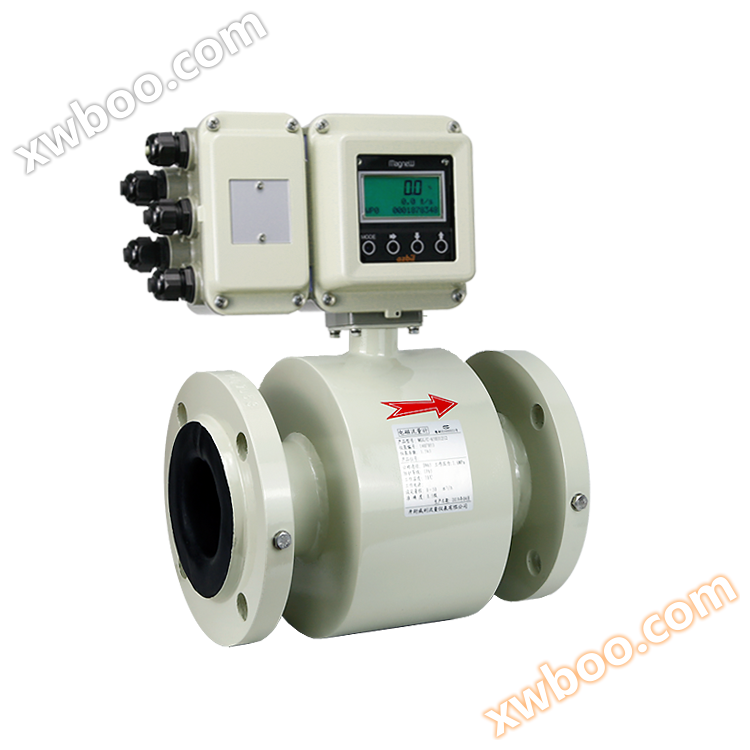
Electromagnetic flow meters are widely used in various fields such as sewage, fluorine chemical industry, production water, tap water industry, as well as pharmaceuticals, steel and many others. Due to its principle, it can only measure conductive liquids
Product Details
Product parameters
Structure:
The structure of an electromagnetic flowmeter mainly consists of a magnetic circuit system, a measuring conduit, electrodes, a housing, a lining, and a converter.
Magnetic circuit system: Its function is to generate a uniform DC or AC magnetic field. The DC magnetic circuit is implemented using permanent magnets, which has the advantages of a relatively simple structure and less interference from AC magnetic fields. However, it can easily polarize the electrolyte liquid inside the measuring tube, causing the positive electrode to be surrounded by negative ions and the negative electrode to be surrounded by positive ions, resulting in electrode polarization and an increase in internal resistance between the two electrodes, which seriously affects the normal operation of the instrument. When the diameter of the pipeline is large, the permanent magnet is also large, bulky, and uneconomical. Therefore, electromagnetic flow meters generally use alternating magnetic fields and are excited by a 50HZ power supply.
Measurement catheter: Its function is to allow the measured conductive liquid to pass through. In order to divert or short-circuit the magnetic flux when the magnetic field lines pass through the measuring conduit, the measuring conduit must be made of non-magnetic, low conductivity, low thermal conductivity, and materials with certain mechanical strength, such as non-magnetic stainless steel, fiberglass, high-strength plastic, aluminum, etc.
Electrode: Its function is to generate an induced potential signal proportional to the measured value. The electrode is generally made of non-magnetic stainless steel and is required to be flush with the lining so that fluid can pass through without obstruction. Its installation position should be in the vertical direction of the pipeline to prevent sediment from accumulating on it and affecting measurement accuracy.
Shell: Made of ferromagnetic material, it is the outer shell of the distribution system excitation coil and isolates the interference of external magnetic fields.
Lining: There is a complete layer of electrical insulation lining on the inner side of the measuring conduit and the flange sealing surface. It directly contacts the liquid being measured, and its function is to increase the corrosion resistance of the measuring conduit and prevent the induced potential from being short circuited by the metal measuring conduit wall. The lining materials are mostly corrosion-resistant, high-temperature resistant, wear-resistant polytetrafluoroethylene plastics, ceramics, etc.
Converter: The induced potential signal generated by liquid flow is very weak and greatly affected by various interference factors. The function of the converter is to amplify and convert the induced potential signal into a unified standard signal and suppress the main interference signal. Its task is to amplify and convert the induced potential signal Ex detected by the electrode into a unified standard DC signal.
characteristic
1. Measurement is not affected by changes in fluid density, viscosity, temperature, pressure, and conductivity;
2. There are no obstructing flow components or pressure loss inside the measuring tube, and the requirements for straight pipe sections are relatively low. Has unique adaptability to slurry measurement;
3. Reasonably selecting sensor lining and electrode materials, which have good corrosion resistance and wear resistance;
4. The converter adopts a novel excitation method, with low power consumption, stable zero point, and high accuracy. The flow range can reach 150:1;
5. The converter can be integrated or separated from the sensor;
6. The converter adopts a 16 bit high-performance microprocessor, 2x16 LCD display, convenient parameter setting, and reliable programming;
7. The flowmeter is a bidirectional measurement system equipped with three integrators: forward total, reverse total, and differential total; It can display positive and negative flow rates and has multiple outputs: current, pulse, digital communication HART;
8. The converter adopts surface mount technology (SMT) and has self checking and self diagnostic functions;
9. The measurement accuracy is not affected by changes in fluid density, viscosity, temperature, pressure, and conductivity. The sensor's induced voltage signal is linearly related to the average flow rate, resulting in high measurement accuracy.
10. There is no obstruction in the measuring pipeline, so there is no additional pressure loss; There are no movable parts inside the measuring pipeline, so the sensor has an extremely long lifespan.
11. Due to the fact that the induced voltage signal is formed in the entire space filled with a magnetic field and is the average value on the surface of the pipeline, the sensor requires a shorter straight pipe section, with a length of 5 times the diameter of the pipeline.
12. A bidirectional measurement system that can measure both forward and reverse flow rates. Using special production processes and high-quality materials to ensure the stability of product performance over a long period of time.
Instrument parameters:
| Nominal diameter: | DN10~DN3000 |
| Nominal pressure: | 0.6MPa(DN1200~DN2000) 1.0MPa(DN700~DN1000) 1.6MPa(DN200~DN600) 4.0MPa(DN10~DN150) |
| Dielectric conductivity: | ≥5μs/cm |
| Measurement range: | 1500:1 flow rate setting<15m/s |
| Electrode material: | Molybdenum containing stainless steel, Hastelloy B, Hastelloy C, titanium, tantalum, platinum/iridium alloy, stainless steel coated with tungsten carbide |
| Lining material: | Polychloroprene rubber, polytetrafluoroethylene (PTFE), F46, PFA, polyurethane rubber |
| Medium temperature: | Split type: chloroprene rubber lining, polyurethane lining: -10 ℃ to+80 ℃ PTFE lining, PFA lining, F46 lining: -10 ℃~+160 ℃ Integrated: -10 ℃~+80 ℃ |
| Environmental temperature: | Separate type: -25 ℃~60 ℃ Integrated type: -10 ℃~60 ℃ |
| accuracy: | ± 0.5% of indication, optional ± 0.3% or ± 0.2% of indication |
| Shell protection: | IP65, IP68 optional (IP65: dust tight, water-resistant; IP68: Dust tight, capable of continuous immersion in water. ) |
| Explosion proof mark: | ExmbⅡT4 |
| Connection method: | flange |
Lining material:
| Lining material | Performance | scope of application |
|
PTFE (PTFE) |
1. The most chemically stable material in plastics, capable of withstanding boiling hydrochloric acid, sulfuric acid, and aqua regia, as well as concentrated alkali and various organic solvents, but not resistant to corrosion by aluminum trifluoride, high sulfur liquid fluorine, liquid oxygen, and ozone. 2. Poor wear resistance. |
Strong corrosive media such as concentrated acid and alkali |
| PFA |
1. The most chemically stable material in plastics, capable of withstanding boiling hydrochloric acid, sulfuric acid, and aqua regia, as well as concentrated alkali and various organic solvents, but not resistant to corrosion by aluminum trifluoride, high sulfur liquid fluorine, liquid oxygen, and ozone. 2. Strong anti negative pressure ability. |
Can be used in negative pressure state |
| F46 |
1. The most chemically stable material in plastics, capable of withstanding boiling hydrochloric acid, sulfuric acid, and aqua regia, as well as concentrated alkali and various organic solvents, but not resistant to corrosion by aluminum trifluoride, high sulfur liquid fluorine, liquid oxygen, and ozone. 2. Able to withstand low wear and tear. 3. Strong anti negative pressure ability. |
Strong corrosive media such as concentrated acid and alkali Can be used for low wear media |
| chloroprene rubber |
1. It has excellent elasticity, high tensile strength, and good wear resistance. 2. Resistant to corrosion in general low concentration acid, alkali, and salt media, but not resistant to corrosion in oxidizing media. |
Water, sewage, weakly abrasive mud, weakly abrasive slurry |
| polyurethane |
What is the wear resistance (equivalent to 10 times that of natural rubber). 2. Acid and alkali resistance are relatively poor. 3. Cannot be used in water mixed with organic solvents. |
Neutral and strongly worn slurry, medium slurry, mud, etc |
Corrosion resistance of electrode materials:
| Electrode material | Corrosion resistance performance |
| SUS316 | Used for industrial water, domestic water, sewage, and weakly corrosive media, widely used in industries such as petroleum, chemical, urea, and vinylon. |
| Stainless steel coated with tungsten carbide | Used for non corrosive and highly abrasive media. |
| Hastelloy B (HB) | It has good corrosion resistance to all concentrations of hydrochloric acid below boiling point, as well as to non oxidizing acids, bases, and non oxidizing salt solutions such as sulfuric acid, phosphoric acid, hydrochloric acid, and organic acids. |
| Hastelloy C (HC) | Capable of withstanding corrosion from oxidizing acids such as nitric acid, mixed acids, or complex acids in mixed media, as well as corrosion from oxidizing salts such as Fe++, Cu++, or other oxidants. Corrosion caused by hypochlorite solutions above room temperature and seawater. |
| Titanium (Ti) | Capable of withstanding corrosion from seawater, various chlorides and hypochlorohydrochloric acid, oxidizing acids (including fuming nitric acid), organic acids, alkalis, etc., but not resistant to corrosion from relatively pure reducing acids (such as sulfuric acid, hydrochloric acid). But if oxidants (such as nitric acid, Fe++, Cu++) are also included in the calculation, the corrosion is greatly reduced. |
| Tantalum (Ta) | It has excellent corrosion resistance and is very similar to glass. It can withstand almost all chemical media (including hydrochloric acid, sulfuric acid, aqua regia) except for hydrochloric acid, fuming nitric acid, and alkali. |
| platinum-iridium | Suitable for almost all chemical substances, but not suitable for aqua regia and ammonium salts. |
Installation method:
Simply put, an electromagnetic flowmeter is composed of a flow sensor transmitter. The installation requirement of electromagnetic flowmeter is to be installed at the lowest point of the pipeline or the vertical section of the pipeline, but it must be installed when the pipeline is full. The requirement for the straight pipe section is the first 5D and then 3D, so as to ensure the use of electromagnetic flowmeter and the accuracy requirements.
The measurement principle of electromagnetic flowmeter does not depend on the characteristics of flow rate. If there is a certain amount of turbulence and vortex generated in the non measurement area of the pipeline (such as bends, tangential flow restrictions, or partially open shut-off valves upstream), it is irrelevant to the measurement. If there is a steady-state eddy current in the measurement area, it will affect the stability and accuracy of the measurement. In this case, some measures should be taken to stabilize the flow velocity distribution:
1. Increase the length of the front and rear straight pipe sections
2. Adopt a traffic stabilizer
3. Reduce the cross-section of measurement points.
1. Requirements for the external environment
1.1. Flow meters should be avoided from being installed in places with large temperature changes or high temperature radiation from equipment. If installation is necessary, insulation and ventilation measures must be taken.
1.2. It is best to install the flowmeter indoors. If it must be installed outdoors, it should be protected from rainwater, waterlogging, and direct sunlight. Moisture and sun protection measures should be taken.
1.3. Flow meters should be avoided from being installed in environments containing corrosive gases, and ventilation measures must be taken when installation is necessary.
1.4. For the convenience of installation, maintenance, and upkeep, there should be ample installation space around the flowmeter.
1.5. The installation site of the flowmeter should avoid magnetic fields and strong vibration sources. If the pipeline vibration is large, there should be fixed pipe supports on both sides of the flowmeter.
1. 2. Pipeline electromagnetic flowmeter
2.1. Requirements for straight sections
In order to improve the effects of eddy currents and flow field distortions, there are certain requirements for the length of the straight pipe sections before and after the installation of the flowmeter, otherwise it will affect the measurement accuracy (rectifiers can also be installed, avoiding installation near the regulating valve and half open valve as much as possible).
2.2. Requirements for process pipes
The flowmeter has certain requirements for the upstream and downstream process pipes of the installation point, otherwise it will affect the measurement accuracy.
a. The inner diameter of the upstream and downstream process pipes should be the same as that of the sensor, and should meet the requirement of 0.98DN ≤ D ≤ 1.05DN (where DN is the inner diameter of the sensor and D is the inner diameter of the process pipe)
b. The process pipe and sensor must be concentric, and the coaxial deviation should not exceed 0.05DN
2.3. Requirements for bypass pipes
For the convenience of repairing flow meters, it is best to install a bypass pipe for the flow meter. In addition, for heavily polluted fluids and flow meters that need to be cleaned but cannot be stopped, a bypass pipe must be installed.
a. Convenient maintenance of flow meters
b. Heavy pollution fluids must be installed
c. The fluid cannot stop and the flow meter needs to be cleaned
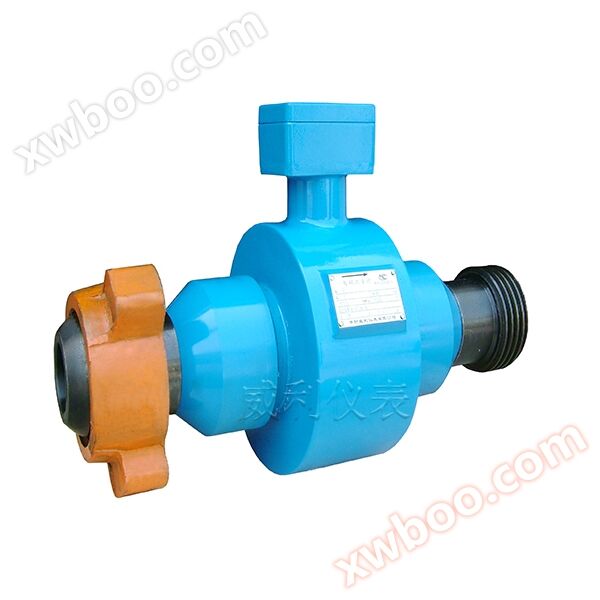
3. Installation requirements for plug-in electromagnetic flowmeter
3.1. Requirements for straight pipe sections
Inlet/outlet straight pipe section: The inlet should be ≥ 10 × DN; the outlet should be ≥ 5 × DN
3.2. Requirements for docking location
In order to ensure the reliable operation of the instrument, improve measurement accuracy, and avoid interference from external parasitic potentials, the sensor should have a good grounding resistance of less than 10. (If the metal pipeline is well grounded, there is no need to set up a dedicated grounding device.) 3.3 The installation position requirements are shown in the figure
The insertion of electromagnetic flow meters varies depending on the on-site pipeline conditions. Flow meters without ball valves should be installed on pipelines without pressure (i.e. flow meters without ball valves can be selected for installation without pressure). A hole with a diameter of 50 should be opened on the pipeline, and the connecting welded pipe should be welded to the opening of the pipeline; For situations that require continuous loading and unloading or do not allow medium overflow, ball valves must be installed, that is, plug-in electromagnetic flow meters with ball valve structures should be selected; Drill a hole with a diameter of 50 on the pipeline and prepare to weld the connecting welded pipe onto the opening of the pipeline.
Selection of plug-in electromagnetic flowmeter
Measurement range: Recommended usage range: 0.5m/s to 10m/s, continuously adjustable. Maximum usage range: 0.2m/s~15m/s continuously adjustable
Signal output: 1. The switch value can be set to pulse output (up to 1000Hz); High/low traffic alarm; Air traffic control alarm; Flow direction indication;
Fault alarm; 2. Current output: 4-20mA output
Configuration method: 1. Configure on-site through three manual keys. 2. Configure on-site through remote control. 3. Configure on-site through a handheld device.
Memory: EEPROM is a memory that does not disappear and does not require battery storage.
explain:
Electromagnetic flow meters are widely used in various fields such as sewage, fluorine chemical industry, production water, tap water industry, as well as pharmaceuticals, steel and many others. Due to its principle, it can only measure conductive liquids. Although it is much better in reliability and stability than other types of flow meters, customers still encounter some problems during actual use. Below, I will explain in detail the selection and installation of electromagnetic flow meters:
1、 Like other flow meters, although the measurement range ratio of electromagnetic flow meters is 30:1, which is higher than vortex flow meters and differential pressure flow meters, it is also limited. Many customers often compare it with water meters when ordering a meter, thinking that it can measure very low flow rates. Generally, it can only measure 0.1m/s. Below this flow rate, electromagnetic flow meters are difficult to measure correctly. So in the initial stage of ordering, it is necessary to clarify the flow range. When placing an order, it is not advisable to order according to the original pipe diameter. It is better to determine the instrument diameter based on your actual flow rate.
2、 Like other flow meters, electromagnetic flow meters also have requirements for straight pipelines before and after installation, although the requirements are lower than other types of flow meters. However, the most crucial point is to meet the requirement of full pipe and then full pipe. Insufficient flow can easily cause the flowmeter to jump:
3、 Like other flow meters, electromagnetic flow meters also have protection levels. Generally, the protection level for integrated flow meters is IP65, and for split type flow meters (for sensors) it is IP68. If customers have requirements for the installation environment of the instrument and the installation location is in underground manholes or other humid places, it is recommended that customers choose split type flow meters. To avoid selecting the wrong one and causing damage to the instrument.
4、 Electromagnetic flow meters can measure corrosive liquids, but in the initial stage of ordering, customers need to provide the correct properties of other measuring media to avoid errors in electrode selection during selection, which may result in the sensor being scrapped during later use, causing inconvenience and economic losses to customers.
5、 Although electromagnetic flow meters have good reliability and are generally not damaged, due to their principle, the sensor electrode surface is always in contact with the liquid, and over time, the electrode surface is more susceptible to contamination. Therefore, in general, for electromagnetic flowmeters, if customers have the conditions to disassemble them, it is recommended to remove and clean the electrodes once every one to one and a half years to ensure the measurement accuracy of the entire flowmeter. Any instrument requires maintenance, and electromagnetic flow meters are no exception.
6、 When the main pipeline is a vertical pipeline, it is generally required that the water flow should be from bottom to top, and should not be from top to bottom as much as possible. The latter can easily cause significant fluctuations in traffic. In addition to filling the pipes, this is also very important for installation, followed by the distance between the front and rear straight pipes.
Choose a place that is easy to maintain and has convenient activities. The flowmeter should be installed at the rear end of the water pump and must not be installed on the suction side; The valve should be installed on the downstream side of the flow.
Previous product:MGG Intelligent Electromagnetic Converter
Next product:MGG paper specific electromagnetic flowmeter
Similar Product Recommend