-
E-mail
sales@szqianjia.com
-
Phone
13751049325
-
Address
Room 107, Building C, Chaoloft Cultural and Creative Park, No. 150 Huayue Road, Langkou Community, Dalang Street, Longhua District, Shenzhen City
Product Categories
Shenzhen Qianjia Technology Co., Ltd
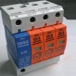
OBO V25-B/1+NPE/AS/FS B-class power lightning arrester
NegotiableUpdate on 10/03
- Model
- Nature of the Manufacturer
- Producers
- Product Category
- Place of Origin
Overview
The OBO V25-B high-energy lightning arrester contains a special varistor circuit composed of zinc oxide varistors with excellent nonlinear characteristics (30).
Product Details
V25-BTechnical parameters of lightning arrester
NPEModule technical parameters
V25-BLightning arrester function
The OBO V25-B high-energy lightning arrester contains a special varistor circuit composed of zinc oxide varistors with excellent nonlinear characteristics (>30). This enables the lightning arrester to achieve maximum protection even under high-energy overvoltage surges. Its protection level is that under a 100KA/10As impact, the residual voltage does not exceed 2kV. Therefore, this lightning arrester can withstand partial lightning current from direct lightning strikes. When a line overload occurs, the circuit breaker inside the lightning arrester will automatically disconnect the failed lightning arrester module from the main circuit, and the color of the display window used to monitor the working status on the module will change from green to red.
V25-BApplication of lightning arrester
When the building itself is equipped with an external lightning protection system (such as installing lightning rods, down conductors, grounding grids, and external shielding), according to the relevant theories of IEC and VDE, OBO V25-B/3+NPE/FS is used to establish lightning protection equipotential connections on the power lines of the 380V/230V low-voltage distribution circuit inside the building, which can avoid the hazards of fire, explosion, and personal injury caused by lightning.
V25-BSpecial configuration of lightning arrester
AS sound and light alarm moduleA functional base with sound and light alarms, supplying a 220V single-phase mains power to the base. Under normal circumstances, the light displays green, etc. When a module is damaged, the alarm light changes from green to a flashing red light, accompanied by a "beep beep" alarm sound, reminding maintenance personnel to replace it.
FSRemote signaling contact moduleEquipped with a remote signaling contact function base, terminals 1-2 (normally open contacts) or 1-3 (normally closed contacts) can be selected for connection according to actual needs. And terminal wiring can use 0.14-2.5mm2 multi strand wire or single core wire.
The AS sound and light alarm module and FS remote signaling contact module enable maintenance personnel to monitor the working status of lightning arresters in real time. When the lightning arrester is found to be malfunctioning, maintenance personnel only need to replace the faulty lightning arrester module, which can reduce maintenance costs and does not require a power outage during replacement.
Basic requirements for installation specifications
1. Installation location: V25-B should be installed in the low-voltage main distribution cabinet of the computer room, parallel to the outgoing side of the main circuit breaker.
2. The length of the connecting wire between the lightning arrester and the power supply system should be less than 50cm. The length of the lightning arrester and the ground wire should also be less than 50cm
3. Selection of wire cross-section (according to VDE0100 standard) Unit: mm2
4. Due to the characteristics of V25-B/3+NPE/FS, it is recommended to connect a backup circuit breaker in series before the lightning arrester. The recommended capacity of the circuit breaker is 32A, Class A circuit breaker (such as Siemens 5sx2332-5)
5. The wiring installation of FS has three wiring ports, with terminals 1-2 being normally closed contacts and terminals 1-3 being normally closed contacts. Different terminals are connected according to the different user alarm devices.
Attention: It is not allowed to wire protected lines in parallel with unprotected lines or ground wires.
| model | V25-B |
| Normal operating voltage UN | 230V~ |
| Maximum continuous operating voltage UcAC UcDC |
385 505 |
| According to VDE 0675, Part 6 classification level | B |
| Voltage protection level Up under 5KA (8/20) surge current | <1.0KV |
| Maximum throughput of a single module Imax (8/20us) | 60KA |
| According to the IEC1312-1 and ENV61024-1 standards, the measurement value is measured using the (10/350) direct lightning pulse current waveform test Peak current ismax Electricity Q 特定能量 W/R |
25KA 12.5AS 160 KJ/W |
| Maximum fuse specification capable of withstanding a short-circuit current of 25Karpm | 160A gl |
| Selection range of connecting wires | 2.5-35mm2 |
| install | According to DIN EN50052 standard requirements, fixed on a 35mm wide metal guide rail |
| Color module base |
orange grey |
| 700g | |
| material | polyimide |
| Volume (length * width * height) | 90mm*89mm*62mm |
| Rated reactive DC voltage UagN | 500V±20% |
| Rated working voltage Ur | 250V~ 50/60HZ |
| Insulation resistance Riso at 100V | >10 Gohm |
| According to IEC 529 lightning current test (10/350) The maximum flow rate is max Electricity Q Specific energy W/R |
25KA 12.5As 160 KJ/Ω |
| 最大通流量 (8/20us) Is max | 50KA |
| 100% lightning surge response voltage (1.2/50) UAS 100 | ≤1KV |
| Protection level | ≤1KV |
| Reaction time tA | ≤100 ns |
| Temperature range for use | -40℃-----+80℃ |
V25-BLightning arrester function
The OBO V25-B high-energy lightning arrester contains a special varistor circuit composed of zinc oxide varistors with excellent nonlinear characteristics (>30). This enables the lightning arrester to achieve maximum protection even under high-energy overvoltage surges. Its protection level is that under a 100KA/10As impact, the residual voltage does not exceed 2kV. Therefore, this lightning arrester can withstand partial lightning current from direct lightning strikes. When a line overload occurs, the circuit breaker inside the lightning arrester will automatically disconnect the failed lightning arrester module from the main circuit, and the color of the display window used to monitor the working status on the module will change from green to red.
V25-BApplication of lightning arrester
When the building itself is equipped with an external lightning protection system (such as installing lightning rods, down conductors, grounding grids, and external shielding), according to the relevant theories of IEC and VDE, OBO V25-B/3+NPE/FS is used to establish lightning protection equipotential connections on the power lines of the 380V/230V low-voltage distribution circuit inside the building, which can avoid the hazards of fire, explosion, and personal injury caused by lightning.
V25-BSpecial configuration of lightning arrester
AS sound and light alarm moduleA functional base with sound and light alarms, supplying a 220V single-phase mains power to the base. Under normal circumstances, the light displays green, etc. When a module is damaged, the alarm light changes from green to a flashing red light, accompanied by a "beep beep" alarm sound, reminding maintenance personnel to replace it.
FSRemote signaling contact moduleEquipped with a remote signaling contact function base, terminals 1-2 (normally open contacts) or 1-3 (normally closed contacts) can be selected for connection according to actual needs. And terminal wiring can use 0.14-2.5mm2 multi strand wire or single core wire.
The AS sound and light alarm module and FS remote signaling contact module enable maintenance personnel to monitor the working status of lightning arresters in real time. When the lightning arrester is found to be malfunctioning, maintenance personnel only need to replace the faulty lightning arrester module, which can reduce maintenance costs and does not require a power outage during replacement.
Basic requirements for installation specifications
1. Installation location: V25-B should be installed in the low-voltage main distribution cabinet of the computer room, parallel to the outgoing side of the main circuit breaker.
2. The length of the connecting wire between the lightning arrester and the power supply system should be less than 50cm. The length of the lightning arrester and the ground wire should also be less than 50cm
3. Selection of wire cross-section (according to VDE0100 standard) Unit: mm2
| Distribution power cord | ≤35 | 50 | ≥70 |
| connect wires | 10 | 16 | 25 |
| ground wire | ≥16 | 25 | ≥35 |
5. The wiring installation of FS has three wiring ports, with terminals 1-2 being normally closed contacts and terminals 1-3 being normally closed contacts. Different terminals are connected according to the different user alarm devices.
Attention: It is not allowed to wire protected lines in parallel with unprotected lines or ground wires.
Similar Product Recommend