-
E-mail
jsyesyb@163.com
-
Phone
13813316363
-
Address
271 Jinhu Huancheng West Road, Huai'an City, Jiangsu Province
Product Categories
Jiangsu Yarson Instrument Co., Ltd
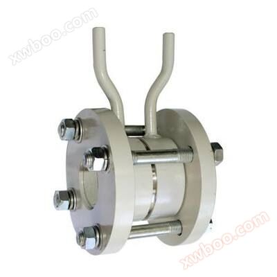
Porous orifice plate flowmeter (balance flowmeter)
NegotiableUpdate on 08/20
- Model
- Nature of the Manufacturer
- Producers
- Product Category
- Place of Origin
Overview
Product Introduction: YSLG-DKB Porous Orifice Plate Flow Meter (also known as Balanced Flow Meter) is a new type of throttling flow sensor developed based on the international GB2624 standard orifice plate and flow regulator. Porous orifice plate flowmeter is used for installation downstream of various disturbances to achieve * * * short straight ..
Product Details
YSLG-DKB Porous Orifice Plate Flow Meter(also known as balance flowmeter) is a new type of throttling flow sensor developed based on the standard orifice plate and flow regulator according to international GB2624. Porous orifice flow meters are used for installation downstream of various disturbances, providing excellent performance with short straight pipe sections.
Principle of YSLG-DKB porous orifice flowmeter:
Porous orifice plate is also a type of differential pressure flow meter, which works on the same principle as other differential pressure flow meters, based on energy conversion in sealed pipelines.
Under ideal fluid conditions, the flow rate in a pipeline is proportional to the square root of the differential pressure; The flow rate in the pipeline can be calculated based on the Bernoulli equation by measuring the differential pressure value. The porous orifice plate flow sensor is a porous disc throttling rectifier installed on the cross-section of the pipeline. When the fluid passes through the rectifying holes of the disc, it will be balanced and distilled, and the vortex will be minimized to form an approximately ideal fluid. Through a pressure measuring device, a stable differential pressure signal can be obtained, and the volume flow rate and mass flow rate can be calculated according to the Bernoulli equation.
Parameters required for selection of porous orifice flow meter (balance flow meter):
1. Pipe diameter: pipe diameter, wall thickness
2. Measurement medium
3. Medium temperature (° C)
4. Medium pressure (MPa): * * * high pressure, normal pressure, * * * low pressure
5. Medium working flow rate (Nm3/h): * * * large, * * * small, normal flow rate
6. Medium viscosity (mPa. S)
7. Medium density (kg/m3)
8. Pressure collection method
Installation requirements:
1. Measure liquid flow rate
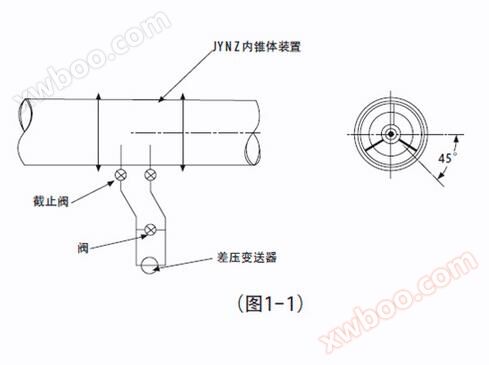
(a) The differential pressure transmitter should be installed below the inner cone device (Figure 1.1) to prevent gas in the liquid from entering the pressure pipe and transmitter.
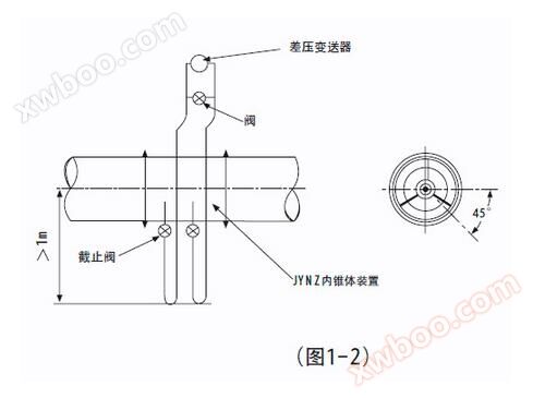
(b) If the transmitter has to be installed above the inner cone device (Figure 1.2), in order to reduce the gas in the liquid entering the pressure pipe, a U-shaped bend should be installed between the inner cone device and the pressure pipe, and the lower end of the bend should be located 1 meter from the center of the pipeline.
(c) On horizontal or inclined pipelines, if the pressure pipe is installed in the upper half of the inner cone fixture, gas will accumulate inside the pressure pipe. If it is installed in the lower half of the inner cone device It will cause sediment to fall into the pressure conduit. Therefore, the pressure pipe should be led out from both ends of the horizontal centerline of the inner cone installation. Or lead out from a horizontal angle of less than 45 degrees downwards.
2. Measure steam flow rate
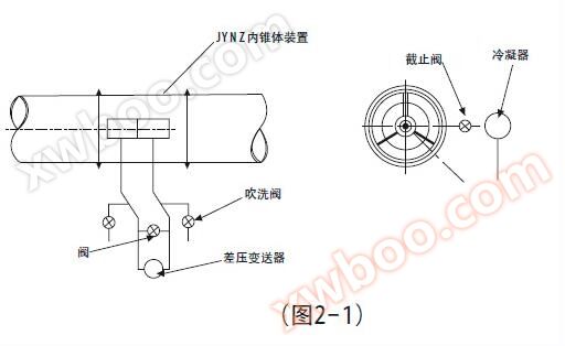
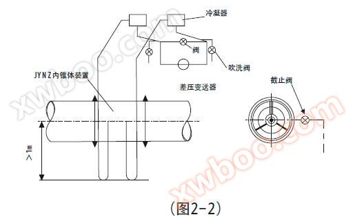
(a) In order to ensure that the transmitter is not affected by high steam temperature, two condensers located at the same height must be installed between the transmitter and the inner cone device, and the condenser, pressure pipe, and high and low pressure chambers must be filled with condensed water to avoid the impact of high temperature on the transmitter.
(b) The differential pressure transmitter should be installed below the inner cone device (Figure 2.1) to prevent gas from entering the pressure pipe and transmitter The condenser should be installed as close as possible to the inner cone device.
(c) If the differential pressure transmitter has to be installed above the inner cone device (Figure 2.2), the condenser should be installed above the differential pressure transmitter.
(d) Both installation methods mentioned above are equipped with valves near the transmitter for flushing the pressure pipe At the same time, insulation layer should be added to the pressure pipe between the inner cone device and the secondary condenser.
3. Measure gas flow rate
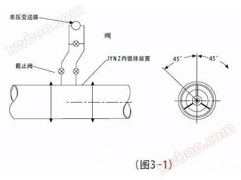
(a) The differential pressure transmitter should be installed above the inner cone device (Figure 3.1), so that the condensate generated in the pressure pipe can flow back into the pipeline.
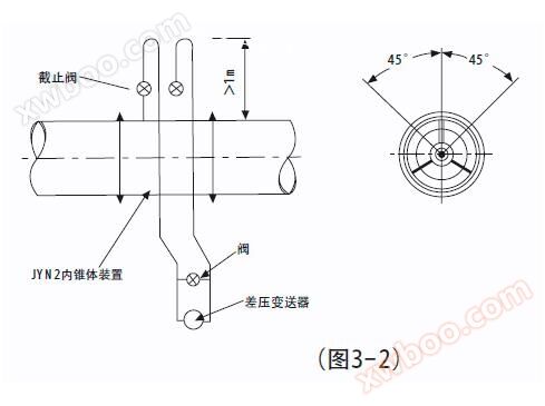
(b) If the transmitter has to be installed below the inner cone device (Figure 3.2), in order to reduce water condensation in the pressure pipe, a U-shaped bend should be installed from the pressure pipe leading out of the inner cone device, and the upper end of the bend should be at least 1 meter higher than the management center.
(c) On horizontal or inclined pipelines, in order to prevent condensation from entering the pressure pipe, the pressure pipe should be led out from the half of the horizontal centerline of the inner cone device body.
(d) If the gas contains dirt or dust, a cross joint should be installed at the turning point of the pressure pipe for cleaning or blowing.
Similar Product Recommend