-
E-mail
jsyesyb@163.com
-
Phone
13813316363
-
Address
271 Jinhu Huancheng West Road, Huai'an City, Jiangsu Province
Product Categories
Jiangsu Yarson Instrument Co., Ltd
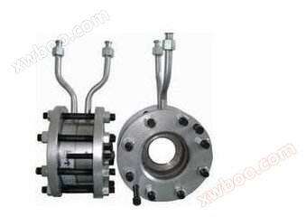
Standard orifice steam flowmeter
NegotiableUpdate on 08/20
- Model
- Nature of the Manufacturer
- Producers
- Product Category
- Place of Origin
Overview
Product Introduction: In a standard orifice steam flowmeter, the main element composed of the connection between the orifice and the pipeline, as well as the adjacent pressure parts, is formed by a differential pressure device combined with some mechanisms for translating pressure to obtain a flow rate and indication result. In some cases, the combination of recorded graphics is significant ..
Product Details
In a standard orifice plate steam flowmeter, the main element composed of the orifice, pipeline, and adjacent pressure connections, while the binary system is composed of a differential pressure device and some mechanisms for translating pressure to obtain a flow rate and indication result. In some cases, the combination of recorded graphics has been used until then. This combination of primary and secondary school elements will be observed in almost all other types of observation tables. Some common positive displacement meters include scales, reciprocating pistons, rotating pistons, swing discs, sliding rotating blades, gears, and Lobed Impellers, as well as meters commonly used for relatively low gas flow rates and bellows flow meters. What is a standard orifice flowmeter? Pressure drops caused by orifice flowmeter conduits and restrictions. An hour glass is a small hole. Nozzles, Venturi tubes, or thin sharp holes can be used as flow limiters. Proper use of these devices is necessary for measurement and empirical calibration. That is to say, transmit a known volume. Provide a measurement standard for other quantities for reading through annotations. Due to its ease of replication and simple construction, thin sharp holes have been adopted as standard and extensive calibration work has been completed, making it widely accepted as a standard method for measuring fluids. It is necessary to provide standard mechanical construction without further calibration. Measure the pressure loss (differential) at a pipeline outlet using a pressure gauge as shown in Figure 1 when the fluid passes through a through-hole.
Overview
The standard orifice steam flowmeter is a differential pressure generating device for measuring flow rate, which can be used in conjunction with various differential pressure gauges or transmitters to measure the flow rate of various fluids in pipelines. The standard orifice flowmeter throttling device includes a ring chamber orifice plate, nozzle, etc. The orifice flowmeter throttling device is used in conjunction with differential pressure transmitters to measure the flow rates of liquids, vapors, and gases, and is widely used in industries such as petroleum, chemical, metallurgical, power, and light industry.
When the fluid filled in the pipeline flows through the throttling device inside the pipeline, the flow beam will form a local contraction at the throttling element of the throttling device, thereby increasing the flow velocity and lowering the static pressure. As a result, a pressure drop, or pressure difference, is generated before and after the throttling element. The larger the flow rate of the medium, the greater the pressure difference generated before and after the throttling element. Therefore, standard orifice flow meters can measure the size of fluid flow by measuring the pressure difference. This measurement method is based on the laws of energy conservation and flow continuity.
The intelligent throttling device (standard orifice flowmeter) is a new generation flowmeter that integrates flow rate, temperature, and pressure detection functions, and can automatically compensate for temperature and pressure. This standard orifice flowmeter uses advanced microcomputer technology and low-power new technology, with strong functions, compact structure, simple operation, and convenient use.
Characteristics of standard orifice steam flowmeter:
The structure of the orifice plate flowmeter throttling device is easy to replicate, simple and sturdy, with stable and reliable performance, long service life, and low price.
▲ Orifice plate calculation adopts international standards and processing
The orifice flowmeter has a wide range of applications, and can measure all single-phase flows, as well as some mixed phase flows.
The standard throttling device does not require real flow calibration and can be put into use.
The installation of the integrated orifice flowmeter is simpler, without the need for a pressure pipe, and can be directly connected to differential pressure transmitters and pressure transmitters.
▲ Adopting imported monocrystalline silicon intelligent differential pressure sensor
▲ High precision, comprehensive self diagnostic function
▲ Intelligent orifice flowmeter The range of the intelligent orifice flowmeter can be self programmed and adjusted.
The intelligent orifice flowmeter can simultaneously display cumulative flow rate, instantaneous flow rate, pressure, and temperature.
In addition to online and dynamic full compensation functions, the intelligent orifice flowmeter also has self diagnosis and self setting range.
▲ Equipped with multiple communication interfaces
▲ High stability
▲ Wide range, greater than 10:1
Structural form of standard orifice steam flowmeter:
1. The flange pressure tapping, corner joint pressure tapping, and D-D/2 pressure tapping methods are shown in Figure 1, Figure 2, and Figure 3, respectively. Please refer to the specific product details for details
Technical specifications of intelligent standard orifice flowmeter:
▲ High precision: ± 0.075%
▲ High stability: better than 0.1% FS/year
▲ High static pressure: 40MPa
▲ Work continuously for 5 years without the need for calibration
▲ Temperature and static pressure effects can be ignored
▲ Anti high overvoltage
Scope of application of standard orifice steam flowmeter:
1. Nominal diameter: 50mm ≤ DN ≤ 1200mm (exceeding this range is considered a non-standard throttling device)
2. Nominal pressure: PN ≤ 16MPa
3. Aperture ratio: 0.20 ≤ β ≤ 0.75
4. Reynolds number range: 5000 ≤ ReD when 0.20 ≤ β ≤ 0.45
When 0.45 ≤ β ≤ 0.75, 10000 ≤ ReD
5. Accuracy: Level 1
Selection of standard orifice steam flowmeter
| model | Explanation | ||||||||
| LG | Throttle device (orifice flowmeter) | ||||||||
| code name | Two basic classifications based on their structural features | ||||||||
| K | orifice plate | ||||||||
| P | Nozzles, etc | ||||||||
| code name | Nominal pressure (105Pa) | ||||||||
| 2.5 | 2.5 | ||||||||
| 10 | 10 | ||||||||
| 16 | 16 | ||||||||
| 25 | 25 | ||||||||
| 64 | 64 | ||||||||
| 100 | 100 | ||||||||
| 200 | 200 | ||||||||
| code name | Caliber (mm) | ||||||||
| 10~1600 | 10~1600mm | ||||||||
| code name | Subdivide according to its structural form | ||||||||
| H | Standard orifice plate (ring chamber) | ||||||||
| Y | Standard orifice plate (flange) | ||||||||
| K | Standard orifice plate (drilling) | ||||||||
| I | ISA 1932 nozzle | ||||||||
| L | Long diameter nozzle | ||||||||
| W | Wenqiu Li nozzle | ||||||||
| G | Classic Wenqiu Li Guan | ||||||||
| S | Double orifice plate | ||||||||
| Q | Circular perforated plate | ||||||||
| Z | conical entrance orifice plate | ||||||||
| R | 1/4 round hole plate | ||||||||
| P | Eccentric orifice plate | ||||||||
| N | Integrated (concealed) orifice plate | ||||||||
| X | Wedge-shaped orifice plate | ||||||||
| T | Special throttling devices not listed above | ||||||||
| code name | medium | ||||||||
| 1 | liquid | ||||||||
| 2 | gas | ||||||||
| 3 | steam | ||||||||
| 4 | High temperature liquid | ||||||||
| code name | Compensation form | ||||||||
| N | Without pressure or temperature compensation | ||||||||
| P | With pressure compensation output | ||||||||
| T | Equipped with temperature compensation output | ||||||||
| Q | Equipped with pressure and temperature compensation output | ||||||||
| code name | Differential pressure range of transmitter | ||||||||
| 0 | Micro differential pressure range | ||||||||
| 1 | Low differential pressure range | ||||||||
| 2 | Medium differential pressure range | ||||||||
| 3 | High differential pressure range | ||||||||
| code name | Is there an on-site display | ||||||||
| W | Throttle device sensor | ||||||||
| X | Intelligent throttling device (flowmeter) | ||||||||
Installation requirements for standard orifice flowmeter:
1. During installation, it should be ensured that the center of the orifice plate, flange center, pipeline center, and gasket are concentric, and the eccentricity should not exceed 0.002D/β.
2. The positive and negative pressure directions of the orifice plate, as well as the upstream and downstream pressure tapping flanges, should be consistent with the flow direction of the medium. The orientation of the pressure tapping holes can be determined according to the different media and the installation of the transmitter.
3. When connecting the throttling device to the pipeline, the non perpendicularity between the welding end face and the pipeline axis shall not exceed 1 °. After welding, the internal weld seam should be processed to make it smooth and free of welding bars and slag.
4. Before welding the pressure tapping flange to the pipeline, the pressure tapping hole on the pipeline should be drilled with the same diameter as the pressure tapping hole on the pressure tapping flange. During welding, the pressure tapping hole on the pressure tapping flange should be aligned with the pressure tapping hole on the pipeline.
5. Optional upstream and downstream straight pipe sections.
6. D-D/2 pressure tapping is supplied as a complete set, and flange connection can be directly installed.
Similar Product Recommend