-
E-mail
cdysyb@163.com,@qq.com
-
Phone
18908016281,13980818230
-
Address
No. 1001, Zone A, No. 1299 Tianfu Avenue South, High tech Zone, Chengdu City
Product Categories
Chengdu Hengshengyuan Technology Co., Ltd

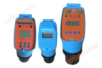
HT100BX split type ultrasonic level gauge
NegotiableUpdate on 09/22
- Model
- Nature of the Manufacturer
- Producers
- Product Category
- Place of Origin
Overview
The HT100BX series ultrasonic liquid (substance) meter is an intelligent non-contact liquid (substance) level measuring instrument. The product has adjustable transmission power, full range gain control, automatic temperature compensation, and other functions. It also uses unique detection and calculation methods to identify false signals and effectively remove various interference signals. Application areas: Water and sewage treatment: pump rooms, collection wells, biochemical reaction tanks, sedimentation tanks, mud storage tanks, etc. Power, mining: mortar tanks, coal slurry tanks, water treatment
Product Details
Durable and stable sensors suitable for harsh industrial environments;
• Advanced algorithm integrating rich field experience can effectively overcome field interference such as foam and surge;
The ultrasonic transducer adopts imported piezoelectric ceramic materials and acoustic matching technology to improve emission efficiency;
The transducer is equipped with a built-in temperature sensor to achieve real-time automatic temperature compensation of the measured values;
Program controlled automatic emission energy adjustment takes into account both large range and small blind spots;
Blind spots can also be manually set to block interference signals near the probe;
4~20mA isolated current output, optional fieldbus interface.
Technical Indicators:
Resolution: 1mm/1cm
Measurement error: 0.2% (full range)
Display mode: Dual row 14 bit LCD (with backlight)
Signal output: Two channels of DC4-20mA current
One channel of DC4-20mA current, one channel of RS485 serial communication
(Determined by the selected model)
Load resistance: 0-500 Ω
Relay output: upper limit, lower limit alarm and control
Fault relay: liquid level detection fault alarm
Relay mode: normally open
Number of relays: 4
Relay specification: 5A 250VAC/30VDC
Serial communication: RS485 standard level
Power supply:
MD:DC24V(±10%) 0.1A
MA:AC220V(±20%) 0.1A
Detection cycle: 1 second (adjustable)
Environmental temperature: -40 ℃ -+85 ℃
Shell material: ABS
Shell protection level: IP67
Cable gland: PG9/PG11/PG13.5
Parameter setting method: 3-digit sensitive button
Installation method: wall mounted
Dimensions: 186X183X126mm (as shown in the picture)
Ultrasonic level gauge includes two parts: transmitter (secondary instrument) and sensor (sensor cable customized according to the site, instrument with 10 meters)
The installation of the transmitter should pay attention to the following points: Please note when installing ultrasonic sensors: The installation diagram is as follows:
1. Special attention should be paid to avoiding direct sunlight, excessive vibration, direct exposure to rainwater, proximity to large motors, or exposure to strong electromagnetic fields on the transmitter.
2. The output signal line of the instrument must be dual core shielded
3. Instruments must have strict grounding.
4. Leave sufficient space for the opening and maintenance of the transmitter enclosure.
5. As much as possible, the transmitter should be installed slightly above the operator's level of sight, which will facilitate normal instrument inspection or control operations.
Ultrasonic transmitters are generally mounted by hanging, using three positioning holes behind the instrument, as shown in the following figure
1. The emission surface of ultrasonic sensors must be horizontal;
2. The installation height of ultrasonic sensors should be less than the range of the instrument;
3. The height from the surface of the ultrasonic sensor to the highest liquid level should be greater than the blind spot of the instrument;
4. The distance from the ultrasonic sensor to the pool wall, riverbank, and embankment generally needs to be greater than 0.5 meters. If the wall is not smooth and has obvious protrusions, it is necessary to increase the distance appropriately;
5. The installation position of the sensor should avoid areas directly below where there are significant fluctuations in the liquid level, such as the inlet and outlet ports;
6. If the requirements of 4) and 5) cannot be met, it is necessary to consider installing PVC pipes with a diameter of about 100mm on site and placing the sensors of the instrument in the PVC pipes.