-
E-mail
wxbrck@ 163.com
-
Phone
13812024099
-
Address
No. 35 Xigang East Road, Xishan District, Wuxi City
Product Categories
Jiangsu Borui Measurement and Control Technology Co., Ltd
Platinum Ray Temperature and Pressure Compensation Vortex Flow Meter - Wuxi Platinum
NegotiableUpdate on 11/13
- Model
- Nature of the Manufacturer
- Producers
- Product Category
- Place of Origin
Overview
1、 Overview of Temperature and Pressure Compensation Vortex Flow Meter Products: Temperature and pressure compensation vortex flow meter is a new type of flow meter developed based on the principle of liquid vibration, widely used in the measurement of fluids in industries such as petroleum, chemical, metallurgy, and papermaking. This flowmeter has no movable parts and can ..
Product Details
1、 Overview of Temperature and Pressure Compensation Vortex Flow Meter Products
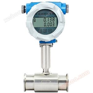
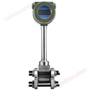
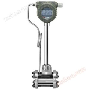
The temperature pressure compensation vortex flowmeter is a new type of flowmeter developed based on the principle of liquid vibration, widely used in the measurement of fluids in industries such as petroleum, chemical, metallurgy, and papermaking. This flowmeter has no movable parts, strong reliability, high accuracy, and long service life. It can accurately measure the instantaneous flow rate and cumulative flow rate of liquids over a wide flow range. It is not affected by the temperature, pressure, viscosity, and composition of the medium, and is not blocked, stuck, easy to scale, resistant to high temperature and high pressure, safe and explosion-proof, suitable for harsh environments. Integrated display and remote transmission of flow scoring, and can output pulse signals or current signals to connect with PLC control system as shown in Figure 1.

Figure 1
3、 Flow Range Table of Temperature and Pressure Compensation Vortex Flow Meter
4、 Outline dimension diagram of temperature and pressure compensation vortex flowmeter
Figure 1
2、 Main characteristics of temperature pressure compensation vortex flowmeter
1. The structure is simple and sturdy, with no movable parts, high reliability, and very reliable for long-term operation.
2. Easy to install and very convenient to maintain.
3. The detection sensor does not directly contact the measured medium, with stable performance and long lifespan.
4. The output is a pulse signal proportional to the flow rate, with no zero drift and high accuracy.
5. The measurement range is wide, and the range ratio can reach 1:10.
6. Less pressure loss, lower operating costs, and more energy-saving significance.
7. Within a certain Reynolds number range, the output signal frequency is not affected by the physical properties and composition changes of the fluid. The instrument coefficient is only related to the shape and size of the vortex generator, and there is no need to compensate when measuring the fluid volume flow rate. After replacing the accessories, there is generally no need to recalibrate the instrument coefficient.
8. Widely applicable, the flow rates of steam (saturated steam), gases (air, oxygen, nitrogen, coal gas, natural gas, gas, hydrogen, liquefied petroleum gas, hydrogen peroxide, flue gas, methane, butane, chlorine, gas, biogas, carbon dioxide, nitrogen, acetylene, phosgene, oxygen, compressed air, argon, toluene, benzene, xylene, hydrogen sulfide, sulfur dioxide, ammonia), steam, liquids and water, liquids (water, high-temperature water, oil, food liquids, chemical liquids, etc.), liquids, and gases can be measured.
3、 Flow Range Table of Temperature and Pressure Compensation Vortex Flow Meter
Table 1: Liquids and Gases (Unit: m)3/h)
|
path (DN) |
Liquid flow range (m3/h) |
Output frequency range (Hz) |
Gas flow range (m3/h) |
Output frequency range (Hz) |
|
15 |
1.2~6.2 |
90~900 |
5~25 |
265~2640 |
|
20 |
1.5~10 |
40~396 |
8~50 |
218~1982 |
|
25 |
1.6~16 |
32~325 |
10~70 |
172~1420 |
|
32 |
2~20 |
20~250 |
15~150 |
130~1350 |
|
40 |
2.5~25 |
13~130 |
22~220 |
115~1147 |
|
50 |
3.5~35 |
9~93 |
36~320 |
96~854 |
|
65 |
6~60 |
8~82 |
50~480 |
61~583 |
|
80 |
10~100 |
6~65 |
70~640 |
45~417 |
|
100 |
15~150 |
5~50 |
130~1100 |
43~367 |
|
125 |
25~250 |
5~47 |
200~1700 |
33~290 |
|
150 |
40~400 |
4~40 |
280~2240 |
27~221 |
|
200 |
80~800 |
3~33 |
580~4960 |
24~207 |
|
250 |
140~1400 |
3~26 |
970~8000 |
20~171 |
|
300 |
200~2000 |
2~22 |
1380~11000 |
17~136 |
4、 Outline dimension diagram of temperature and pressure compensation vortex flowmeter
|
path (DN) |
L (mm) |
H (mm) |

|
|||||||||
|
10 |
66 |
360 |
||||||||||
|
15 |
66 |
360 |
||||||||||
|
20 |
66 |
360 |
||||||||||
|
25 |
66 |
360 |
||||||||||
|
32 |
66 |
365 |
||||||||||
|
40 |
80 |
370 |
||||||||||
|
50 |
80 |
375 |
||||||||||
|
65 |
93 |
383 |
||||||||||
|
80 |
100 |
390 |
||||||||||
|
100 |
125 |
400 |
||||||||||
|
125 |
145 |
470 |
||||||||||
|
150 |
165 |
500 |
||||||||||
|
200 |
196 |
580 |
||||||||||
|
250 |
235 |
650 |
||||||||||
|
300 |
255 |
700 |
||||||||||
|
5、 Installation diagram |
||||||||||||
|
Precautions |
Legend |
|||||||||||
|
1. Installation of expansion pipe For small diameters and large flow rates, it is necessary to expand the pipe installation and ensure that the front straight pipe section of the flowmeter is ≥ 15D and the rear straight pipe section is ≥ 5D |
|
|||||||||||
|
2. Installation of shrink tubing For large caliber and small flow, it is necessary to install a reduction pipe, while ensuring that the front straight pipe section of the flowmeter is ≥ 15D and the rear straight pipe section is ≥ 5D |
|
|||||||||||
|
3. Installation of bent pipes If the front end of the flowmeter has a 90 ° elbow or T-shaped joint, it is necessary to ensure that the front straight pipe section of the flowmeter is ≥ 15D and the rear straight pipe section is ≥ 5D |
|
|||||||||||
|
4. Installation of two bent pipes on the same plane If there are two 90 ° elbows at the front end of the flowmeter, it is necessary to ensure that the front straight pipe section of the flowmeter is ≥ 20D and the rear straight pipe section is ≥ 5D |
|
|||||||||||
|
5. Installation of two curved pipes in different planes If there are two 90 ° elbows at the front end of the flowmeter, it is necessary to ensure that the front straight pipe section of the flowmeter is ≥ 25D and the rear straight pipe section is ≥ 5D |
|
|||||||||||
|
6. Installation of regulating valve If regulating valves need to be installed before and after the flowmeter, it is necessary to ensure that the front straight pipe section of the flowmeter is ≥ 25D and the rear straight pipe section is ≥ 5D |

|
|||||||||||
|
VI. Product Selection |
||||||||||||
|
LUGB |
vortex flow meter |
|||||||||||
|
caliber (mm) |
10 |
DN10~DN50 (flange type, clamp type, threaded type, clamp type) |
||||||||||
|
50 |
DN50~DN150 (clamp type, flange type) |
|||||||||||
|
100 |
DN100~DN300 (flange type, clamp type) |
|||||||||||
|
300 |
DN300 and above are plug-in type |
|||||||||||
|
Installation method |
B |
clamp-on |
||||||||||
|
L |
Flange connection type |
|||||||||||
|
C |
plug-in |
|||||||||||
|
compensation method |
none |
No compensation |
||||||||||
|
BC |
Temperature and pressure compensation |
|||||||||||
|
W |
Single temperature compensation |
|||||||||||
|
Y |
Single pressure compensation |
|||||||||||
|
measuring medium |
Y |
liquid |
||||||||||
|
Q |
gas |
|||||||||||
|
Z |
steam |
|||||||||||
|
temperature range |
T1 |
Room temperature type (below 120 ℃) |
||||||||||
|
T2 |
High temperature type (below 250 ℃) |
|||||||||||
|
pressure rating |
P1 |
Normal pressure~1.6MPa |
||||||||||
|
P2 |
2.5MPa |
|||||||||||
|
P3 |
4.0MPa |
|||||||||||
|
body material |
A |
carbon steel |
||||||||||
|
B |
304 stainless steel |
|||||||||||
|
C |
316 stainless steel |
|||||||||||
|
power supply method |
D |
Two wire system DC24V 4-20mA |
||||||||||
|
H |
Two wire DC24V 4-20mA+HART protocol |
|||||||||||
|
C |
battery-powered |
|||||||||||
|
Additional options |
R |
RS485 MODBUS communication protocol |
||||||||||
|
M |
pulse output |
|||||||||||
|
B |
Explosion proof (ExII CT6) |
|||||||||||


7、 Technical specifications of temperature pressure compensation vortex flowmeter
1. Measurement media: liquid, gas, saturated vapor, superheated vapor.
2. Accuracy level: ± 1.0% for liquids, ± 1.5% for gases (vapors), ± 2.5% for insertions.
3. Working pressure: 1.6MPa, 2.5MPa, 4.0MPa, 6.4MPa.
4. Medium temperature: Ordinary type -40~150 ℃ Medium temperature type -40~250 ℃ High temperature type -40~350 ℃.
5. Output signal: Three wire voltage pulse, low level 0-1V, high level>4V, duty cycle 50%; The standard current for two-wire system is 4-20mA; the standard current for two-wire system is 0-10mA.
6. Working environment: -35 ℃~+60 ℃, humidity ≤ 95% RH.
7. Working power supply: DC12V; DC24V。
8. Shell material: carbon steel, stainless steel.
9. Explosion proof type: intrinsic safety ExibIICT6.
8、 Installation techniques for temperature and pressure compensation vortex flowmeter
8、 Installation techniques for temperature and pressure compensation vortex flowmeter
1. The upstream and downstream piping should be concentric with the inner diameter of the flow meter body, and the different axial degrees between them should be less than 0.05D.
2. The sealing gasket between the instrument and the flange should not protrude into the pipe during installation, and its inner diameter should be 1-2mm larger than the inner diameter of the body
3. Installation design of pressure and temperature measuring holes. When temperature and pressure transmitters need to be installed on the tested pipeline, the pressure measuring hole should be set at 3-5D downstream, and the temperature measuring hole should be set at 6-8D downstream,
4. Instruments can be installed horizontally, vertically, or diagonally on pipelines.
5. When measuring gas, instruments are installed in vertical pipelines with no restrictions on gas flow direction. But if the pipeline contains a small amount of liquid, in order to prevent the liquid from entering the instrument measuring tube, the airflow should flow from bottom to top.
Similar Product Recommend