-
E-mail
wxbrck@ 163.com
-
Phone
13812024099
-
Address
No. 35 Xigang East Road, Xishan District, Wuxi City
Product Categories
Jiangsu Borui Measurement and Control Technology Co., Ltd
Platinum Ray Vortex Flow Meter - Wuxi Platinum Ray Measurement and Control
NegotiableUpdate on 11/13
- Model
- Nature of the Manufacturer
- Producers
- Product Category
- Place of Origin
Overview
1、 The working principle of LUGB vortex flowmeter is mainly used for flow measurement of various media such as gas, liquid, vapor, etc. in industrial pipelines. Its characteristics are small pressure loss, large measurement range, high accuracy, and almost no dependence on fluid density when measuring volumetric flow rate under working conditions ..
Product Details
1、 Working principle
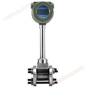
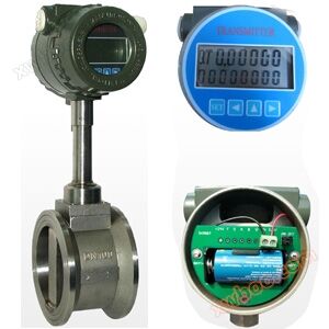
LUGB vortex flowmeter is mainly used for flow measurement of industrial pipeline medium fluids, such as gas, liquid, vapor and other media. Its characteristics are small pressure loss, large range, high accuracy, and almost unaffected by parameters such as fluid density, pressure, temperature, viscosity, etc. when measuring volumetric flow rate under working conditions. No movable mechanical parts, therefore high reliability and low maintenance. The instrument parameters can remain stable for a long time as shown in Figure 1.The vortex flowmeter adopts a piezoelectric stress sensor, which has high reliability and can operate within the working temperature range of -50 ℃ to+350 ℃It has both analog standard signals and digital pulse signal outputs, making it easy to use in conjunction with digital systems such as computers. It is a relatively advanced and ideal flow meter.

Figure 1
2、 Technical parameters
1. Measurement medium: gas, liquid, vapor;
2. The caliber specification for flange card mounted calibers is 25, 32, 50, 80, and 100;
3. The selection of flange connection caliber is 100, 150, 200;
4. The normal measurement range for flow rate is Reynolds number 1.5 × 10⁴ to 4 × 10⁶; Gas velocity of 5-50m/s; Liquid 0.5-7m/s;
5. Measurement accuracy of 1.0 level and 1.5 level;
6. Temperature of the tested medium: normal temperature -25 ℃ -100 ℃; 7. High temperature -25 ℃~150 ℃ -25 ℃~250 ℃;
7. Output signal pulse voltage output signal high level 8-10V low level 0.7-1.3V;
8. Pulse duty cycle of about 50%, transmission distance of 100m;
9. Pulse current remote transmission signal 4-20 mA, transmission distance of 1000m;
10. Instrument operating environment temperature: -25 ℃~+55 ℃ humidity: 5-90% RH50 ℃;
11. Material: stainless steel, aluminum alloy;
12. Power supply DC24V or lithium battery 3.6V;
3、 Flow Range Table
3、 Flow Range Table
Table 1: Liquids and Gases (Unit: m)3/h)
|
path (DN) |
Liquid flow range (m3/h) |
Output frequency range (Hz) |
Gas flow range (m3/h) |
Output frequency range (Hz) |
|
15 |
1.2~6.2 |
90~900 |
5~25 |
265~2640 |
|
20 |
1.5~10 |
40~396 |
8~50 |
218~1982 |
|
25 |
1.6~16 |
32~325 |
10~70 |
172~1420 |
|
32 |
2~20 |
20~250 |
15~150 |
130~1350 |
|
40 |
2.5~25 |
13~130 |
22~220 |
115~1147 |
|
50 |
3.5~35 |
9~93 |
36~320 |
96~854 |
|
65 |
6~60 |
8~82 |
50~480 |
61~583 |
|
80 |
10~100 |
6~65 |
70~640 |
45~417 |
|
100 |
15~150 |
5~50 |
130~1100 |
43~367 |
|
125 |
25~250 |
5~47 |
200~1700 |
33~290 |
|
150 |
40~400 |
4~40 |
280~2240 |
27~221 |
|
200 |
80~800 |
3~33 |
580~4960 |
24~207 |
|
250 |
140~1400 |
3~26 |
970~8000 |
20~171 |
|
300 |
200~2000 |
2~22 |
1380~11000 |
17~136 |
4、 Product Selection Table
| model | path | ||||
| LUGB | DN15-900 | ||||
| code name | Installation method | ||||
| A1 | Card mounted type | ||||
| A2 | flanged | ||||
| A3 | plug-in | ||||
| code name | Tested medium | ||||
| B1 | liquid | ||||
| B2 | gas | ||||
| B3 | steam | ||||
| code name | Material of flow probe | ||||
| C1 | 304 | ||||
| C2 | 316 | ||||
| code name | Sensor material | ||||
| K1 | 304 | ||||
| K2 | 316 | ||||
| code name | accuracy class | ||||
| E1 | Level 1.0 | ||||
| E2 | Level 1.5 | ||||
| code name | signal output | ||||
| F1 | 4-20Ma (two-wire system) | ||||
| F2 | 4-20Ma (three wire system) | ||||
| F3 | RS485 communication | ||||
| F4 | RS485 Modbus | ||||
| F5 | HART | ||||
| F6 | Frequency output | ||||
| F7 | on-site display | ||||
| F8 | 4-20mA+frequency+RS485 | ||||
| code name | temperature and pressure compensation | ||||
| N | No temperature and pressure compensation | ||||
| Y | Temperature and pressure compensation | ||||
| code name | temperature | ||||
| T1 | Room temperature type | ||||
| T2 | Medium temperature type | ||||
| T3 | high-temperature type | ||||
| code name | pressure rating | ||||
| P3 | 1.6MPa | ||||
| P4 | 2.5MPa | ||||
| P5 | 4.0MPa | ||||
| P6 | 6.3MPa | ||||
| code name | power supply | ||||
| D1 | Powered by a 3.6V battery | ||||
| D2 | DC24V power supply | ||||
| code name | Protection level | ||||
| U1 | IP65 non explosion proof | ||||
| U3 | IP65 explosion-proof | ||||
Note: For diameters above DN300, it is recommended to use a plug-in vortex flowmeter, which can be customized.
5、 Installation specifications
A vortex flowmeter is a measuring instrument for gases, liquids, and vapors. Proper installation of a vortex flowmeter can better enhance its performance.
1. Reasonably choose the installation site and environment.
Avoid strong electrical equipment, high-frequency equipment, and strong power switch devices; Avoid the influence of high temperature heat sources and radiation sources, avoid strong vibration areas and corrosive environments, and consider easy installation and maintenance.
2. There must be sufficient straight pipe sections upstream and downstream.
If there are two 90 ° elbows on the same plane upstream of the sensor installation point, then: the upstream straight pipe section is ≥ 25D, and the downstream straight pipe section is ≥ 5D.
If there are two 90 ° elbows on different planes upstream of the sensor installation point, then: the upstream straight pipe section is ≥ 40D, and the downstream straight pipe section is ≥ 5D.
The regulating valve should be installed 5D downstream of the sensor. If it must be installed upstream of the sensor, the upstream straight pipe section of the sensor should not be less than 50D, and the downstream should not be less than 5D.
3. The piping upstream and downstream of the installation point should be concentric with the sensor, and the coaxial deviation should not be less than 0.5DN.
4. The pipeline adopts vibration reduction measures.
Sensors should be avoided as much as possible from being installed on pipelines with strong vibrations, especially lateral vibrations. If installation is necessary, vibration reduction measures must be taken by installing pipeline fastening devices and adding anti vibration pads at the upstream and downstream 2D positions of the sensor.
5. Installation on horizontal pipelines is the most commonly used installation method for flow sensors.
When measuring gas flow, if the measured gas contains a small amount of liquid, the sensor should be installed at a higher position in the pipeline.
When measuring liquid flow rate, if the measured liquid contains a small amount of gas, the sensor should be installed at a lower part of the pipeline.
6. Installation of sensors in vertical pipelines.
When measuring gas flow, the sensor can be installed on a vertical pipeline with no restrictions on the flow direction. If the tested gas contains a small amount of liquid, the gas flow should be from bottom to top.
When measuring liquid flow rate, the liquid flow direction should be from bottom to top: this will not add additional liquid weight to the probe.
VIInstallation precautions
Vortex flow meters are sensitive to flow velocity distribution distortion, rotational flow, and flow pulsation in pipelines. Therefore, the installation conditions of pipelines on site should be fully taken into account, and the requirements of the manufacturer's instructions should be followed.
1. Vortex flowmeter can be installed indoors or outdoors. If installed in underground wells, there is a possibility of flooding, and submersible sensors should be selected. Sensors can be installed horizontally, vertically, or obliquely on pipelines, but when measuring liquids and gases, attention should be paid to the installation position to prevent interference from bubbles and droplets,
2. The vortex flowmeter must ensure that the upstream and downstream straight pipe sections have the necessary length. There are differences in data in various materials, which may be due to the fact that the vortex generator has not been standardized, and the impact of differences in shape and size remains to be verified; The experimental research on the necessary length of straight pipe sections for various types of flow blocking components is still insufficient, that is, it is not yet mature. Compared with throttling differential pressure flow meters, this work is still in its initial stage.
3. Connection between sensors and pipelines. Pay attention to the following issues when connecting with pipelines.
a、 The inner diameter D of the upstream and downstream piping is the same as the inner diameter D 'of the sensor, and the difference satisfies the following condition: 0.95D ≤ D' ≤ 1.1D.
b、 The piping should be concentric with the sensor, and the coaxiality should not be less than 0.05D '
c、 The sealing gasket cannot protrude into the pipeline, and its inner diameter can be 1-2mm larger than the inner diameter of the sensor
7、 Product price
Price has always been a topic of concern for everyone. Different models of vortex flowmeters can be found online, but many vortex flowmeter manufacturers have different standard prices. The price is directly related to the medium, pressure, temperature, diameter, and installation method. The diameter is proportional to the price, and the larger the diameter, the higher the price. The final quotation still depends on the actual working conditions on site. Platinum Rui will provide you with the most favorable price and quality service!
7、 Product price
Price has always been a topic of concern for everyone. Different models of vortex flowmeters can be found online, but many vortex flowmeter manufacturers have different standard prices. The price is directly related to the medium, pressure, temperature, diameter, and installation method. The diameter is proportional to the price, and the larger the diameter, the higher the price. The final quotation still depends on the actual working conditions on site. Platinum Rui will provide you with the most favorable price and quality service!
Similar Product Recommend