-
E-mail
wxbrck@ 163.com
-
Phone
13812024099
-
Address
No. 35 Xigang East Road, Xishan District, Wuxi City
Product Categories
Jiangsu Borui Measurement and Control Technology Co., Ltd

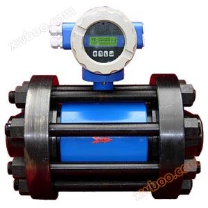
Platinum Ray Welded Orifice Flow Meter - Wuxi Platinum Ray Measurement
NegotiableUpdate on 09/10
- Model
- Nature of the Manufacturer
- Producers
- Product Category
- Place of Origin
Overview
1、 Product Overview of Welded Orifice Flow Meter HW Welded Orifice Plate can be used for measuring the flow of liquids, gases, and vapors in pipelines. The standard orifice plate is designed and manufactured according to the national standard GB/T2624-93 and verified according to JJG640-94. No real flow calibration is required. Standard orifice plate is acceptable ..
Product Details
1、 Overview of Welded Orifice Flow Meter Products
HW welded orifice plates can be used for measuring the flow of liquids, gases, and vapors in pipelines. The standard orifice plate is designed and manufactured according to the national standard GB/T2624-93 and verified according to JJG640-94. No real flow calibration is required. Standard orifice plates can use three pressure measurement methods: corner joint pressure measurement (including ring chamber pressure measurement), flange pressure measurement, or D-D/2 pressure measurement. According to national standards, the design, manufacturing, and calibration of standard orifice plates do not require actual flow calibration, with high accuracy, simple structure, low manufacturing cost, but significant pressure loss. Standard orifice plates are widely used in industries such as petroleum, chemical, metallurgical, and power. It is the most widely used flowmeter so far.
2、 Application, Characteristics, and Scope of Welded Orifice Flow Meter
1. Purpose: The throttling differential pressure flowmeter consists of three parts: throttling device, differential pressure transmitter, and flow accumulator. The throttling device is a primary element directly installed on the pipeline, and the differential pressure transmitter and integrator are secondary elements. It is mainly used for the flow of various gases (pure or dusty), steam (saturated or superheated), and liquids (conductive or non-conductive; highly corrosive; viscous or containing tiny particles of dirt) through pipelines. It can directly measure volumetric flow rate or mass flow rate.
2. The usage conditions, characteristics, and scope of application of differential pressure flowmeter (standard orifice plate)
a、 Usage conditions:
1. In the measurement section, the fluid must fill the circular tube and continuously flow through the throttling device;
2. The fluid must be a homogeneous single-phase fluid both physically and thermodynamically;
3. The fluid measured by the throttling device must be a stable flow, or can be regarded as a stable slowly changing fluid, and is not suitable for pulsating flow and critical flow measurement;
b、 Characteristics and scope of application:
1. The standard throttling device does not require real flow calibration to ensure its measurement accuracy. (Unique among all flow meters);
2. It is widely applicable to the measured medium and can be used for flow measurement of almost all gases, vapors, and liquids;
3. Applicable diameter ratio β is 0.22-0.75, Reynolds number ReD ≥ 5000, pipeline diameter DN50~1000mm, allowing extrapolation to 5000mm. β=d/D, d - orifice plate opening diameter; D - Actual inner diameter of pipeline
4. The pressure can reach up to 32MPa and can also be used for negative pressure;
5. Medium temperature range: -30 ℃ to+650 ℃;
6. The intelligent differential pressure flowmeter adopts an intelligent differential pressure transmitter, which can set the differential pressure value (within the specified range) on site through buttons or communication methods according to the changes in the flow rate of the measured object, thereby changing the flow range and greatly expanding the system flow range;
7. No movable parts, the mechanism is safe and reliable, easy to use and operate, easy to master, and maintenance free;
According to the national standard GB/T2624-93 of the People's Republic of China and the international standard ISO5167-1, the flow range ratio applicable to throttling devices is 3 (i.e. the ratio of maximum and minimum applicable flow rates). In some cases, a range ratio of 4 is allowed. If the range ratio is greater than the above value, the measurement error at low flow rates using the same differential pressure meter will be significant.
IIIWelded orifice flowmeterClassification and structural diagram
1. Classification
① Classified by flange clamping method
1. Welding type 2, flange clamping type
1. Welding type 2, flange clamping type
② Classified by pressure collection method
1. Corner drilling for pressure measurement; 2. Pressure measurement for corner joint chamber 3 and flange pressure measurement; 4. Radial pressure measurement;
2. Structure and schematic diagram
① Figure 1 Structure diagram of standard annular orifice plate throttling device
1. Flange 2, pressure pipe 3, front ring chamber 4, throttling element 5, rear ring chamber 6, sealing gasket 7, bolt 8, nut

Figure 1
Figure 1
4、 Structure and schematic diagram of welded orifice flowmeter
1、 Various standard orifice plate structures, as shown in Figure 2

Figure 2
Figure 2
5、 Product selection of welded orifice flowmeter
| model | Type spectrum description | ||||||||
| BR | enterprise standard | ||||||||
| LG | Flow throttling device | ||||||||
| code name | pressure tapping method | ||||||||
| H | Pressure measurement of corner joint chamber | ||||||||
| Z | Corner drilling for pressure measurement | ||||||||
| F | flange taps | ||||||||
| J | Radial pressure measurement | ||||||||
| code name | Description of throttling device | ||||||||
| K | standard orifice plate | ||||||||
| code name | Nominal Pressure | ||||||||
| -0.6 | 0.6 | ||||||||
| -1 | 1 | ||||||||
| -1.6 | 1.6 | ||||||||
| -2.5 | 2.5 | ||||||||
| code name | Nominal diameter | ||||||||
| DN10 | DN10~DN50 (threaded, flange) | ||||||||
| DN50 | DN50~DN800 (flange) | ||||||||
| code name | flange material | ||||||||
| C | carbon steel | ||||||||
| P | stainless steel | ||||||||
| H | alloy steel | ||||||||
| code name | medium | ||||||||
| 1 | liquid | ||||||||
| 2 | gas | ||||||||
| 3 | steam | ||||||||
| code name | Attachment | ||||||||
| N | Excluding attachments | ||||||||
| F | Equipped with three valve groups, etc | ||||||||
| I | Equipped with F and transmitter (accessories can be selected according to the medium and requirements) | ||||||||
| DC | Equipped with F and multi parameter transmitter | ||||||||
| O | User specified configuration attachments | ||||||||
6、 Installation Techniques for Welded Orifice Flow Meter
1. During installation, it should be ensured that the center of the orifice plate, flange center, pipeline center, and gasket are concentric, and the eccentricity should not exceed 0.002D/β.
2. The positive and negative pressure directions of the orifice plate, as well as the upstream and downstream pressure tapping flanges, should be consistent with the flow direction of the medium. The orientation of the pressure tapping holes can be determined according to the different media and the installation of the transmitter.
3. When connecting the throttling device to the pipeline, the non perpendicularity between the welding end face and the pipeline axis shall not exceed 1 °. After welding, the internal weld seam should be processed to make it smooth and free of welding bars and slag.
4. Before welding the pressure tapping flange to the pipeline, the pressure tapping hole on the pipeline should be drilled with the same diameter as the pressure tapping hole on the pressure tapping flange. During welding, the pressure tapping hole on the pressure tapping flange should be aligned with the pressure tapping hole on the pipeline.
5. Optional upstream and downstream straight pipe sections.
6. D-D/2 pressure tapping is supplied as a complete set, and the flange connection can be directly installed
Similar Product Recommend