-
E-mail
wxbrck@ 163.com
-
Phone
13812024099
-
Address
No. 35 Xigang East Road, Xishan District, Wuxi City
Product Categories
Jiangsu Borui Measurement and Control Technology Co., Ltd
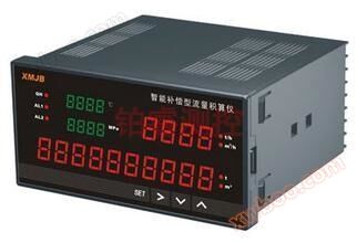
Platinum Rui Intelligent Flow Accumulator - Wuxi Platinum Rui Measurement
NegotiableUpdate on 09/10
- Model
- Nature of the Manufacturer
- Producers
- Product Category
- Place of Origin
Overview
The main features of the intelligent flow integrator are: 1. It is suitable for flow accumulation measurement and control of various liquids, steam, general gases, etc., and for thermal energy measurement and accumulation control of superheated steam/saturated steam. 2. It has multiple input signal functions and can be matched with various differential pressures ..
Product Details
Main features of intelligent traffic integrator
1. Suitable for flow accumulation measurement and control of various liquids, vapors, general gases, etc., suitable for thermal energy measurement and accumulation control of superheated steam/saturated steam.
2. It has multiple input signal functions and can be matched with various differential pressure, pressure, and frequency flow sensors (such as orifice plates, vortex streets, turbines, etc.). Multiple compensation methods can be freely selected (such as temperature compensation, pressure compensation, temperature compensation+pressure compensation, etc.).
3. The input signal type of the instrument can be changed freely, using new jumper free technology. By setting the internal parameters of the instrument, the instrument can be changed from one input signal to another. Further improving the versatility and reliability of the instrument.
4. It has an extremely wide display measurement range, which can display instantaneous flow measurement values, temperature compensation measurement values, pressure compensation measurement values, flow (differential pressure, frequency) measurement values, and flow accumulation measurement values (0~words) in whole five digits, as well as flow accumulation measurement values in whole eleven digits, accurate to three decimal places (0.001) for accumulation. The internal parameters of the instrument can be set to achieve a large accumulation value of 9999999999.99 × 100.
5. Can perform quantitative/batch control on the measuring medium (with start stop reset function); Ensure that the total accumulated amount of data is not lost through software processing.
6. By using the lookup table method for density compensation, high-precision integration control can be fully automated for superheated steam and saturated steam. Multiple flow integration formulas are built-in, which can adapt to various measurement scenarios. The flow coefficient K can also be automatically calculated based on parameter settings, making parameter settings simpler and more accurate.
7. Capable of serial communication output, using standard MODBUS RTU communication protocol for bidirectional communication with various devices with serial input/output, forming a network control system.
technical indicators
1. Suitable for flow accumulation measurement and control of various liquids, vapors, general gases, etc., suitable for thermal energy measurement and accumulation control of superheated steam/saturated steam.
2. It has multiple input signal functions and can be matched with various differential pressure, pressure, and frequency flow sensors (such as orifice plates, vortex streets, turbines, etc.). Multiple compensation methods can be freely selected (such as temperature compensation, pressure compensation, temperature compensation+pressure compensation, etc.).
3. The input signal type of the instrument can be changed freely, using new jumper free technology. By setting the internal parameters of the instrument, the instrument can be changed from one input signal to another. Further improving the versatility and reliability of the instrument.
4. It has an extremely wide display measurement range, which can display instantaneous flow measurement values, temperature compensation measurement values, pressure compensation measurement values, flow (differential pressure, frequency) measurement values, and flow accumulation measurement values (0~words) in whole five digits, as well as flow accumulation measurement values in whole eleven digits, accurate to three decimal places (0.001) for accumulation. The internal parameters of the instrument can be set to achieve a large accumulation value of 9999999999.99 × 100.
5. Can perform quantitative/batch control on the measuring medium (with start stop reset function); Ensure that the total accumulated amount of data is not lost through software processing.
6. By using the lookup table method for density compensation, high-precision integration control can be fully automated for superheated steam and saturated steam. Multiple flow integration formulas are built-in, which can adapt to various measurement scenarios. The flow coefficient K can also be automatically calculated based on parameter settings, making parameter settings simpler and more accurate.
7. Capable of serial communication output, using standard MODBUS RTU communication protocol for bidirectional communication with various devices with serial input/output, forming a network control system.
technical indicators
| Trademark | Model number |
| XL | C80, S80, C90 series |
| input signal | Analog thermocouple: B, E, J, K, S, T, WRe3-25, F2 Resistance: Pt100, Pt100., Cu50, Cu100, BA1, BA2 Current: 0-10mA, 4-20mA, 0-20mA Voltage: 0-5V, 1-5V Pulse waveform: rectangular, sine or triangular wave Amplitude: Optoelectronic isolation, greater than 4V (or as per user requirements) Range: 0-10KHz (or as per user requirements) |
| output signal | Switching quantity: start, stop, reset Analog output · DC 0-10mA (load resistance ≤ 750 Ω) ·DC 4-20mA (load resistance ≤ 500 Ω) ·DC 0-5V (load resistance ≥ 250K Ω) ·DC 1-5V (load resistance ≥ 250K Ω) Alarm output relay control output - relay ON/OFF return differential. AC220V/3A, DC24V/6A (resistive load) Communication output interface method - standard serial bidirectional communication interface: optoelectronic isolation, RS-485, RS-232, etc Baud rate -1200~9600bps, internal free setting using standard MODBUS RTU communication protocol Feed output DC24 ± 1V, load current ≤ 30mA |
| feature | The mathematical model can be found in the appendix of the instruction manual titled "Mathematical Model of Flow Accumulator Control Instrument" Measurement accuracy ± 0.5% FS or ± 0.2% FS Frequency conversion accuracy ± 1 pulse (LMS) is generally better than 0.2% Resolution ± 1 word Measurement range -19999 to 99999 words Display method: Display of instantaneous flow measurement values from 0 to 99999 ·0 to cumulative value display ·-19999-99999 temperature compensation measurement value display ·-19999-99999 pressure compensation measurement value display ·-19999-99999 flow (differential pressure, frequency) measurement value display ·High brightness LED (digital tube) measurement display ·LED working status display Alarm can be selected with relay upper and lower limit alarm outputs, indicated by LED. The alarm method is to bring back the difference (which can be freely set by the user) Quantitative control can select relay flow quantitative control, with LED output indication. Optional relay flow quantitative process control with LED output indication. Temperature compensation 0-50 ℃ digital automatic temperature compensation Printing control is directly connected to a serial printer (TP-16ASH series micro printer), with a printing interface of RS-232 Printing accuracy is the same as instrument accuracy Parameter Setting · Panel Touch Key Numerical Setting ·Save parameter settings after power failure ·Parameter setting value password lock ·After a power outage, the accumulated flow value should be maintained for more than two years, and the set parameters should be maintained Protection method: Automatic reset of power supply under voltage ·Automatic reset for abnormal work (Watch Dog) |
| Usage environment | Environmental temperature 0-50 ℃ Relative humidity ≤ 85% RH · Avoid strong corrosive gases Conventional power supply voltage: AC220V% (50Hz ± 2Hz, linear power supply) Special type · AC90V~265V - Switching power supply ·DC24V ± 2V - Switching Power Supply Power consumption ≤ 5W (powered by AC220V linear power supply) ·≤ 4W (AC90-265V switch power supply) ·≤ 4W (powered by DC24V power supply) |
Intelligent traffic integrator type chart
| Model number | Explanation | ||||||||
| XL | □ | -□ | □ | -□ | □ | □ | -□ | □ | Uncompensated input flow (thermal energy) accumulation display controller |
| Overall dimensions | C801 S801 C901 |
160 × 80mm (horizontal) 80 × 160mm (vertical) 96×96mm |
|||||||
| contact method or Printing method |
0 2 8 3 |
No communication output RS-232C communication port RS-485 communication port RS-232C printing port |
|||||||
| Alarm/transmission output method |
0 2 3 4 5 8 |
No transmission output relay output 4-20mA transmission output 0-10mA transmission output 1-5V transmission output 0-5V transmission output Special requirements for transmission output |
|||||||
| input type | □ | Refer to the 'Input Type Table' | |||||||
| Route 1 alarm method |
N H L B C D |
No alarm upper limit alarm Lower limit alarm (only one alarm method can be selected) Quantitative flow to control - automatic start Quantitative Flow Process Control - Automatic Start Quantitative flow to control - automatic reset |
|||||||
| Route Two alarm method |
N H L B C |
No alarm upper limit alarm Lower limit alarm (only one alarm method can be selected) Quantitative flow to control - manual start Quantitative flow process control - manual start |
|||||||
| Feed output | P | One DC24V output (see note) | |||||||
| power supply method | T W A |
AC90-265V (switch mode power supply) power supply DC24V power supply AC220V power supply (linear power supply) |
|||||||
| measurement accuracy |
B |
0.5% FS ± 1 word (can be omitted) 0.2% FS ± 1 word (please specify) |
|||||||
Input Type Table
| code | input type | measurement range | code | input type | measurement range | Instructions | ||
| A | 4~20mA | -19999-99999 words | B3 | Thermocouple type B | 0~1800℃ | The items listed in this table are large Range, can be within the range By modifying within the scope The second level parameters of the instrument are accurate Quantitative range. |
||
| B | 0~10mA | -19999-99999 words | S | Thermocouple S-type | 0~1600℃ | |||
| C | 1~5V | -19999-99999 words | K | Thermocouple K-type | 0~1300℃ | |||
| D | 0~5V | -19999-99999 words | E | Thermocouple E-type | 0~1000℃ | |||
| M | 0~20mA | -19999-99999 words | T | Thermocouple T-type | -199.9~400.0 | |||
| F | frequency | 0~10KHz | J | Thermocouple J-type | 0~1200℃ | |||
| C1 | Cu50 | -50.0~150.0 | W | Wre3-25 | 0~2300℃ | |||
| C2 | Cu100 | -50.0~150.0 | F2 | High temperature radiation thermocouple | 0~2000℃ | |||
| G | Pt100 | -199.9~650.0 | R | specific | -19999-99999 words | |||
| B1 | BA1 | -199.9~600.0℃ | ||||||
| B2 | BA2 | -199.9~600.0℃ | ||||||
transmit/Alarm output mode
| Code | 0 | 2 | 3 | 4 | 5 | 8 |
| output method | No output | 4~20mA | 0~10mA | 1~5V | 0~5V | Special specifications |
Intelligent flow integrator instrument type chart
| Model number | Explanation | |||||||||||
| XL | □ | □ | -□ | □ | -□ | □ | □ | -□ | □ | □ | □ | Flow (heat flux) integrator controller |
| Overall dimensions | C8 S8 C9 |
160 × 80mm (horizontal) 80 × 160mm (vertical) 96×96mm |
||||||||||
| Control function |
02 03 04 05 |
Equipped with temperature and pressure compensation input Overheated steam with temperature and pressure compensation - lookup table method Saturated steam with temperature and pressure compensation - lookup table method User specific curve compensation - lookup table method |
||||||||||
| contact method or Printing method |
0 2 4 8 3 |
No communication output RS-232C communication port RS-422 communication port RS-485 communication port RS-232C printing port |
||||||||||
| transmit output method |
0 2 3 4 5 8 |
No transmission output 4-20mA transmission output 0-10mA transmission output 1-5V transmission output 0-5V transmission output Special requirements for transmission output |
||||||||||
| traffic input type |
□ | Refer to the 'Input Type Table' | ||||||||||
| Pressure Compensation input type |
□ | Refer to the 'Input Type Table' | ||||||||||
| temperature compensation input type |
□ | Refer to the 'Input Type Table' | ||||||||||
| Route 1 alarm method |
N H L B C D |
No alarm upper limit alarm Lower limit alarm (only one alarm method can be selected) Quantitative flow to control - automatic start Quantitative Flow Process Control - Automatic Start Quantitative flow to control - automatic reset (Only one alarm method can be selected) |
||||||||||
| Route Two alarm method |
N H L B C |
No alarm upper limit alarm Lower limit alarm (only one alarm method can be selected) Quantitative flow to control - manual start Quantitative flow process control - manual start |
||||||||||
| Feed output | P 2P |
One DC24V output (see note) Two channel DC24V output (see note) |
||||||||||
| power supply method | T W A |
AC90-265V (switch mode power supply) power supply DC24V power supply AC220V power supply (linear power supply) |
||||||||||
| measurement accuracy | B | 0.5% FS ± 1 word (can be omitted) 0.2% FS ± 1 word (please specify) |
||||||||||
Instrument communication interface mode
| Code | 0 | 2 | 8 | 3 |
| contact method | No communication | RS-232 communication port | RS-485 communication port | RS-232 printing port |
transmit/Alarm output mode
| Code | 0 | 1 | 2 | 3 | 4 | 5 | 8 |
| output method | No output | relay | 4~20mA | 0~10mA | 1~5V |
Similar Product Recommend