-
E-mail
wxbrck@ 163.com
-
Phone
13812024099
-
Address
No. 35 Xigang East Road, Xishan District, Wuxi City
Product Categories
Jiangsu Borui Measurement and Control Technology Co., Ltd

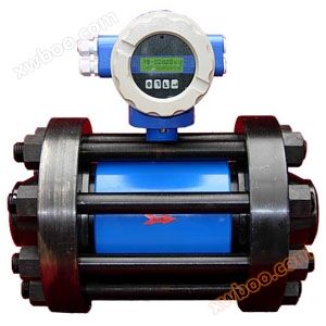
Platinum orifice flowmeter - Wuxi Platinum Measurement and Control
NegotiableUpdate on 09/10
- Model
- Nature of the Manufacturer
- Producers
- Product Category
- Place of Origin
Overview
1、 Product Overview: LG series orifice flowmeter is a differential pressure generating device for measuring flow rate. It can be used in conjunction with various differential pressure gauges or transmitters to measure the flow rate of various fluids in pipelines. The throttling device includes annular orifice plate, nozzle, etc. Orifice flowmeter throttling device and differential ..
Product Details
1、 Product Overview
The LG series orifice flowmeter is a differential pressure generating device for measuring flow rate, which can be used in conjunction with various differential pressure gauges or transmitters to measure the flow rate of various fluids in pipelines. The throttling device includes annular orifice plate, nozzle, etc. The orifice flowmeter throttling device is used in conjunction with a differential pressure transmitter as shown in Figure 1, which can measure the flow rates of liquids, steam, and gases. The orifice flowmeter is widely used in industries such as petroleum, chemical, metallurgy, power, and light industry.

Figure 1
2、 Working principle
When the medium fills the pipeline with fluidWhen they flow through the throttling device inside the pipeline, the flow beam will form a local contraction at the throttling element of the throttling device, thereby increasing the flow velocity and lowering the static pressure. As a result, a pressure drop, or pressure difference, is generated before and after the throttling element. The larger the flow rate of the medium, the greater the pressure difference generated before and after the throttling elementTherefore, the magnitude of fluid flow can be measured by measuring the pressure difference as shown in Figure 2. This measurement method is based on the law of flow continuity.

Figure 2
3、 Purpose, characteristics, and scope of application
1. Purpose: The throttling differential pressure flowmeter consists of three parts: throttling device, differential pressure transmitter, and flow accumulator. The throttling device is a primary element directly installed on the pipeline, and the differential pressure transmitter and integrator are secondary elements. It is mainly used for the flow of various gases (pure or dusty), steam (saturated or superheated), and liquids (conductive or non-conductive; highly corrosive; viscous or containing tiny particles of dirt) through pipelines. It can directly measure volumetric flow rate or mass flow rate.
2. The usage conditions, characteristics, and scope of application of differential pressure flowmeter (standard orifice plate)
a、 Usage conditions:
1. In the measurement section, the fluid must fill the circular tube and continuously flow through the throttling device;
2. The fluid must be a homogeneous single-phase fluid both physically and thermodynamically;
3. The fluid measured by the throttling device must be a stable flow, or can be regarded as a stable slowly changing fluid, and is not suitable for pulsating flow and critical flow measurement;
b、 Characteristics and scope of application:
1. The standard throttling device does not require real flow calibration to ensure its measurement accuracy. (Unique among all flow meters);
2. It is widely applicable to the measured medium and can be used for flow measurement of almost all gases, vapors, and liquids;
3. Applicable diameter ratio β is 0.22-0.75, Reynolds number ReD ≥ 5000, pipeline diameter DN50~1000mm, allowing extrapolation to 5000mm. β=d/D, d - orifice plate opening diameter; D - Actual inner diameter of pipeline
4. The pressure can reach up to 32MPa and can also be used for negative pressure;
5. Medium temperature range: -30 ℃ to+650 ℃;
6. The intelligent differential pressure flowmeter adopts an intelligent differential pressure transmitter, which can set the differential pressure value (within the specified range) on site through buttons or communication methods according to the changes in the flow rate of the measured object, thereby changing the flow range and greatly expanding the system flow range;
7. No movable parts, the mechanism is safe and reliable, easy to use and operate, easy to master, and maintenance free;
4、 Classification and structural diagram
Classification of flange clamping methods:
1. Welding type 2, flange clamping type
Classification of pressure collection methods:
1. Corner drilling for pressure measurement; 2. Pressure measurement for corner joint chamber 3 and flange pressure measurement; 4. Radial pressure measurement;
Structure and schematic diagram:
Structural diagram of standard annular orifice plate throttling device, as shown in Figure 3
1. Flange 2, pressure pipe 3, front ring chamber 4, throttling element 5, rear ring chamber 6, sealing gasket 7, bolt 8, nut

Fig 3
Various standard orifice plate structures and diagrams are shown in Figure 4

Figure 4
Figure 4
5、 Installation skills
Proper installation is beneficial for measuring accuracy and stability, and is crucial for orifice flow meters.
Proper installation is beneficial for measuring accuracy and stability, and is crucial for orifice flow meters.
1. Before installation, it is necessary to verify the on-site operating conditions and confirm that all parameters in the throttling device calculation sheet are exactly the same as the operating conditions at the installation point. Otherwise, necessary corrections or compensations must be made.
2. Direction: There are "+" and "-" marks on the handle of the orifice plate or the outer surface of the flange of the throttling device, respectively. "+" represents the upstream side (facing the direction of the fluid) and must not be installed in reverse.
3. Insertion depth: The pressure tapping hole plate in the ring chamber is inserted at a depth of 2-5mm between the pipeline and the ring chamber, but the pipeline cannot be pushed into the ring chamber, otherwise the pipeline will expand due to heat and damage the ring chamber. Drill a pressure tapping hole plate, and the pipeline protruding into the hole plate must not block the pressure tapping hole at any point.
4. System blowing: After the installation of the throttling device is completed, it should be blown. At this time, the throttling element (orifice plate) should be removed first to prevent debris in the pipeline from scratching the orifice plate or blocking the pressure pipe. After the blowing is completed, it should be installed in the same direction as the arrow on the orifice plate and the direction of fluid flow. Pay attention to tightening to ensure sealing.
5. Zero adjustment: After the purging and installation are completed, open the middle valve of the three valve group. At this time, the differential pressure value should be zero. If not, it must be reset to zero. The method is to hold down the button in the lower left corner for 20 seconds and release it.
6. Finally, slowly close the middle valve of the three valve group (it must be tightly closed), open all the shut-off valves on the upper part of the positive and negative pressure pipes, and the orifice plate can work normally.
7. Installation coaxiality requirements: The throttling element and the pipeline must be concentric, with an eccentricity distance of no more than 0.0025D. Users should pay attention to or take necessary measures during welding operations.
8. Orifice plates are generally used in conjunction with differential pressure transmitters. When connecting the pressure conduit to the differential pressure transmitter, attention should be paid to not installing the positive and negative pressures in reverse, with "H" indicating positive and "L" indicating negative;
9. The pressure pipes led out from the positive and negative pressure ports must be kept parallel in any situation;
10. If a regulating valve must be installed, it is recommended to install the regulating valve after the required length of the straight pipe section on the downstream calculation sheet.
10. If a regulating valve must be installed, it is recommended to install the regulating valve after the required length of the straight pipe section on the downstream calculation sheet.
11. When the measured medium is gas or steam and there are significant fluctuations in temperature and/or pressure, temperature and/or pressure compensation should be performed. The pressure transmitter is installed at 1D upstream, and the thermocouple is installed at 1D downstream.
12. There should be no bag shaped space on the differential pressure signal pipeline where liquid or gas may accumulate. If unavoidable, a gas collector (or exhaust valve) and a settling device (or drain) should be installed.
13. Zero drift of the transmitter can also cause measurement errors, and the differential pressure transmitter should be calibrated regularly during use.
14. Differential pressure pipelines should have brackets to prevent vibration and strong forces from acting on the differential pressure gauge.
15. When lifting the throttling device on site,It is strictly prohibited to use iron wire, steel wire, or hooks to penetrate the throat aperture of the throttling element to prevent sharp mouth damage and affect accuracy;
16. After using the throttling device for a period of time, due to the presence of solid particles in the liquid and liquid droplets or other impurities in the gas, the sharp inlet will be blunted, resulting in an increase in the outflow coefficient and additional errors. At this time, it is necessary to consider replacing the throttling element; In addition, after long-term use, the throttling device is prone to accumulate dirt at the lower corner of the upstream side of the orifice plate, which can cause changes in the outflow coefficient. Therefore, regular inspections should be carried out to eliminate dirt.
17. Pressure tube: The material of the pressure tube should be determined according to the properties and parameters of the measured medium. If the inner diameter is too small or the length is too long, it will cause serious signal lag or distortion,
6、 Product selection
7、 Product price
The price of orifice flow meters is a topic of great concern for every manufacturer. Online quotations vary greatly, with high and low prices.But there are too many factors that determine the price, which are related to the medium, pressure, range, and materialHowever, due to different pressure collection methods and materials, there may be price deviations! The more accurate the parameters provided by the manufacturer, the more accurate the quotation will be. Platinum Rui will serve you with the most favorable price and quality!
6、 Product selection
| model | Type spectrum description | ||||||||
| LG | enterprise standard | ||||||||
| LG | Flow throttling device | ||||||||
| code name | pressure tapping method | ||||||||
| H | Pressure measurement of corner joint chamber | ||||||||
| Z | Corner drilling for pressure measurement | ||||||||
| F | flange taps | ||||||||
| J | Radial pressure measurement | ||||||||
| code name | Description of throttling device | ||||||||
| K | standard orifice plate | ||||||||
| code name | Nominal Pressure | ||||||||
| -0.6 | 0.6 | ||||||||
| -1 | 1 | ||||||||
| -1.6 | 1.6 | ||||||||
| -2.5 | 2.5 | ||||||||
| code name | Nominal diameter | ||||||||
| DN10 | DN10~DN50 (threaded, flange) | ||||||||
| DN50 | DN50~DN800 (flange) | ||||||||
| code name | flange material | ||||||||
| C | carbon steel | ||||||||
| P | stainless steel | ||||||||
| H | alloy steel | ||||||||
| code name | medium | ||||||||
| 1 | liquid | ||||||||
| 2 | gas | ||||||||
| 3 | steam | ||||||||
| code name | Attachment | ||||||||
| N | Excluding attachments | ||||||||
| F | Equipped with three valve groups, etc | ||||||||
| I | Equipped with F and transmitter (accessories can be selected according to the medium and requirements) | ||||||||
| DC | Equipped with F and multi parameter transmitter | ||||||||
| O | User specified configuration attachments | ||||||||
7、 Product price
The price of orifice flow meters is a topic of great concern for every manufacturer. Online quotations vary greatly, with high and low prices.But there are too many factors that determine the price, which are related to the medium, pressure, range, and materialHowever, due to different pressure collection methods and materials, there may be price deviations! The more accurate the parameters provided by the manufacturer, the more accurate the quotation will be. Platinum Rui will serve you with the most favorable price and quality!
Similar Product Recommend